
Micro-polarization array design model and arrangement mode acquisition method thereof

A design model, micro-polarization technology, applied in polarization spectrum, measurement light polarization, measurement device and other directions, which can solve the problems of low image reconstruction quality and frequency domain aliasing error.

Active Publication Date: 2021-01-01
RES & DEV INST OF NORTHWESTERN POLYTECHNICAL UNIV IN SHENZHEN +1
View PDF4 Cites 0 Cited by
  • Summary
  • Abstract
  • Description
  • Claims
  • Application Information

AI Technical Summary

Problems solved by technology

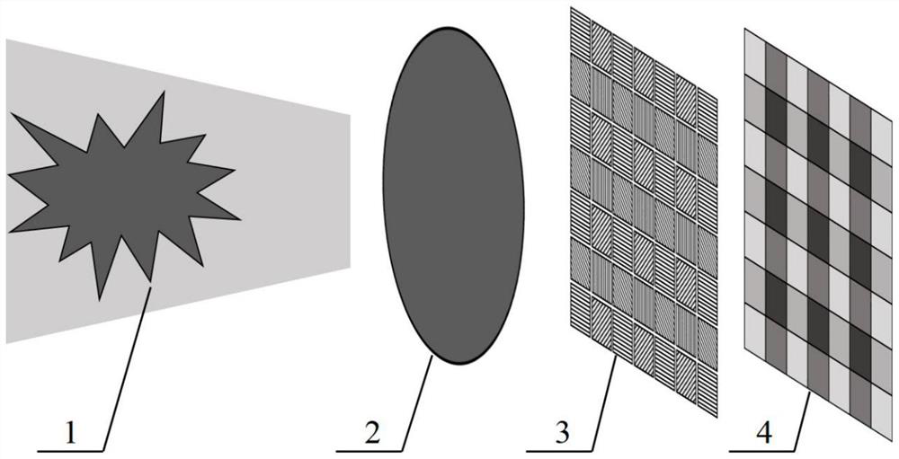
[0007] The purpose of the present invention is to solve the shortcomings of frequency domain aliasing error and low image reconstruction quality in the typical 2×2 micro-polarization array arrangement mode, and the existing design model can only design 2×N series of micro-polarization array structures Limitations, a design model that can cover 2×N series and N×N series micro-polarization array arrangements is proposed, and a new micro-polarization array structure is designed by optimizing the position and bandwidth range of each component in the two-dimensional frequency domain. It aims to improve the quality of Stokes parameter image and DoLP image reconstruction, and meet the requirements of low instantaneous field of view error and high polarization image reconstruction quality in the field of polarization imaging

Method used


Image

  • Micro-polarization array design model and arrangement mode acquisition method thereof
  • Micro-polarization array design model and arrangement mode acquisition method thereof
  • Micro-polarization array design model and arrangement mode acquisition method thereof

Examples


Embodiment Construction

[0071] The embodiment of the present invention provides an example of obtaining the arrangement mode of the micro-polarization array arranged in a 3×3 diagonal arrangement by using a design model. The array structure consists of micro-polarizers with orientation angles of 0°, 60° and 120°, where S A As follows:

[0072]

[0073] Fourier transform is performed on the proposed 3×3 diagonally arranged micro-polarization array structure, and the following formula can be obtained:

[0074]

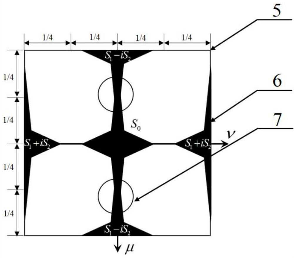
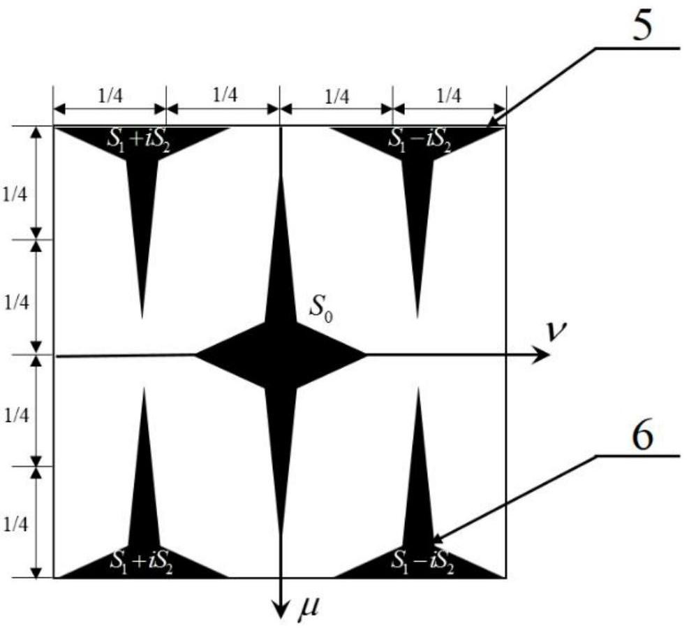
[0075] It can be seen from the above formula that the two-dimensional spectrogram corresponding to the 3×3 array avoids the two frequency components located in the horizontal and vertical directions, increases the distance between the frequency components, and reduces the aliasing error , which can improve the reconstruction quality of Stokes parameter images and DoLP images.

[0076] A 3×3 diagonally arranged micro-polarization array arrangement pattern obtained by the present inventio...


PUM


Abstract

The invention discloses a micro-polarization array design model and an array arrangement mode acquisition method based on the micro-polarization array design model, belongs to the field of polarization optical devices, and mainly relates to a polarization optical technology, a focal plane type polarization imaging detection technology, a Fourier frequency domain optical analysis technology and thelike. According to the model, structural design can be carried out on 2*N series and N*N series micro-polarization arrays, the distances and positions among all components in a two-dimensional frequency domain are optimized by changing parameters a, b and c of the design model, and the bandwidth range among the components which is not influenced by crosstalk is increased, so that the reconstruction quality of Stokes parameter images and DoLP images is improved. According to the design model, from the perspective of two-dimensional frequency domain analysis, the design and acquisition steps ofthe micro-polarization array arrangement mode are simplified, the design range of the array arrangement mode is expanded, a theoretical basis is provided for development of a high-performance micro-polarization array, and high-quality Stokes parameter image reconstruction is realized. And the practical application of the focal plane type polarization imaging system is promoted.

Description

[0001] Technical field [0002] The invention belongs to the field of polarization optics, and mainly relates to polarization optics technology, focal plane polarization imaging detection technology, Fourier frequency domain optical analysis technology and the like. Background technique [0003] Compared with intensity imaging, spectral imaging and other technologies, polarization imaging technology has unique target recognition advantages: in addition to obtaining traditional target imaging information, it can additionally obtain the degree of polarization (DoLP) and angle of polarization (AoP) of the target and background, etc. Information can highlight the contour edge and detail information of the target object, improve the accuracy and probability of target recognition, and has irreplaceable advantages in target detection and recognition compared with other detection methods. Among the existing types of polarization imaging equipment, the focal plane polarization imaging ...

Claims


Application Information

Patent Timeline
IPC IPC(8): G01J3/447G01J4/00G02B27/28
CPCG01J3/447G01J4/00G02B27/286G01J4/04
Inventor 虞益挺郝佳王燕周奎余晓畅
Owner RES & DEV INST OF NORTHWESTERN POLYTECHNICAL UNIV IN SHENZHEN
Learn More