

Power strip capable of reducing copper sheet loss
A technology of copper sheets and sockets, applied in the parts, electrical components, coupling devices of connecting devices, etc., can solve the problems of copper sheet wear, metal fatigue, poor contact, etc. simple effect
- Summary
- Abstract
- Description
- Claims
- Application Information
AI Technical Summary
Problems solved by technology
Method used
Image

Examples
Embodiment Construction
[0014] The present invention will be further elaborated below in conjunction with the accompanying drawings and specific embodiments.
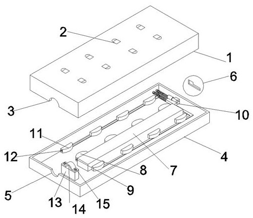
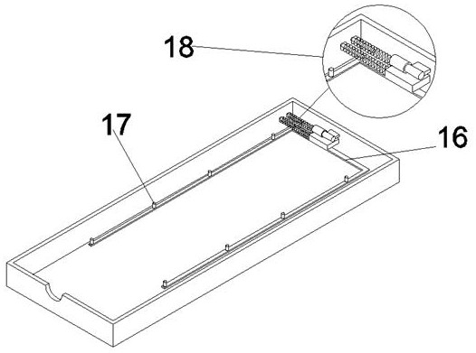
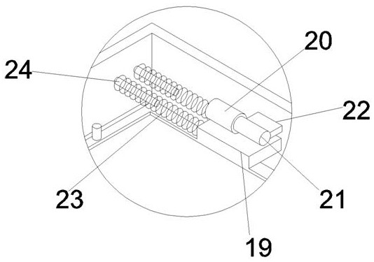
[0015] Such as Figure 1-3 As shown, a plug-in strip for reducing the loss of copper sheets includes a top cover 1, a socket 2, a top cover wire inlet 3, a base 4, a base wire inlet 5, a limit adjustment hole 6, a center bracket 7, and a live wire copper Sheet 8, live wire contact sheet 9, reciprocating limit device 10, zero line copper sheet 11, zero line contact sheet 12, branch line support table 13, branch line pressing sheet 14, pressing and fixing wire 15, the top cover 1 top A plurality of jacks 2 are provided equidistantly on the surface, and the top cover wire inlet hole 3 is opened at the center below the front of the top cover 1, and the base wire inlet hole 5 is opened at the center above the front of the base 4, and the limit adjustment The hole 6 is opened on the back of the base 4, the center bracket 7 is fixedly connected to t...
PUM
 Abstract
Description
Claims
Application Information