A kind of part deep drawing forming method and forming die
A technology for forming molds and parts, applied in the field of deep drawing of parts and forming molds, can solve the problem of high processing cost, achieve the effects of low cost, uniform force, and shorten the processing process of parts
- Summary
- Abstract
- Description
- Claims
- Application Information
AI Technical Summary
Problems solved by technology
Method used
Image
Examples
Embodiment 1
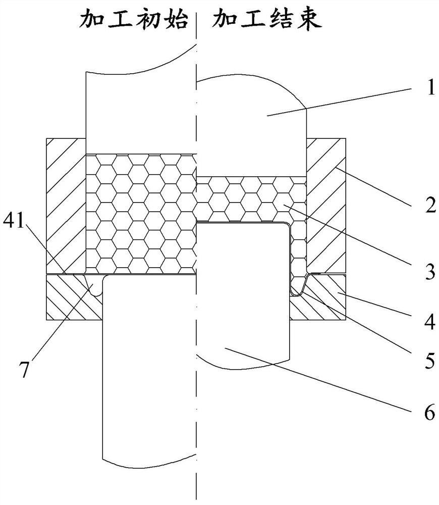
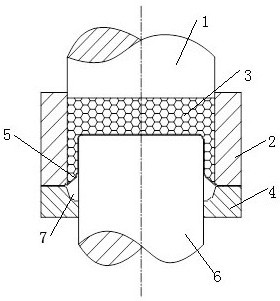
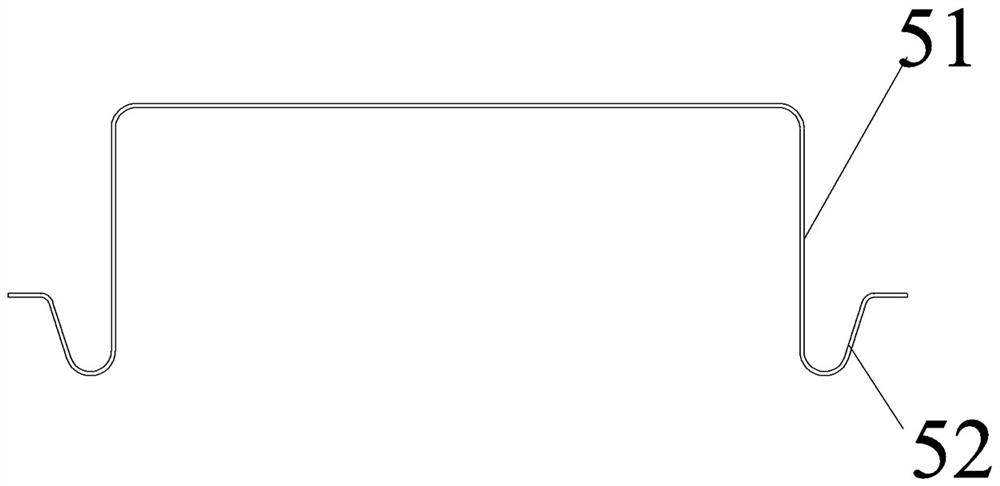
[0041] like Figure 1 to Figure 3 As shown, the forming die in this embodiment is used for deep drawing and forming the intermediate shielding cover of the vacuum interrupter, and the intermediate shielding cover is an existing product, which will not be repeated here. The forming die in this embodiment is specifically used for forming to obtain the following image 3 As shown in the semi-finished product, the intermediate shield can be obtained by performing subsequent punching and crimping processing on the basis of the semi-finished product.
[0042] The forming die specifically includes an upper blank holder 2, a back pressure punch 1, a lower punch 6, a lower die 4 and a particle medium 3, wherein the upper blank holder 2 and the back pressure punch 1 are located on the upper side, and the lower punch is located on the upper side. 6 and the lower die 4 are located on the lower side. When in use, the lower concave die 4 is fixed on the corresponding molding equipment or ...
specific Embodiment 2
[0058] The main difference from Example 1 is that the mold in Example 1 is used to process the intermediate shield, the lower punch is cylindrical, and the forward stretching section is cylindrical. The top of the punch is hemispherical, which is used for cooperating with the back pressure punch to obtain a hemispherical forward drawing section.
[0059] Of course, in other embodiments, the lower punch can also be a truncated circular frustum or a truncated cone structure, and the specific shape can be determined according to the part to be processed.
specific Embodiment 3
[0061] The main difference from Embodiment 1 is that the reverse drawing groove of the lower die in Embodiment 1 is an annular groove, and the outer groove wall of the annular groove is an inclined groove wall, so as to be different from the annular outer groove of the shielding cover. Correspondingly to the turning edge, in this embodiment, the outer groove wall of the reverse deep drawing groove is a vertical groove wall, so as to form a rectangular decoupling strand.
[0062] Of course, in other embodiments, the reverse drawing groove on the lower die can also be of other shapes, such as V-shape or W-shape, as long as it is adapted to the shape of the eversion edge of the part to be formed. The plate is forced to deform by the particle medium to abut against the groove wall of the reverse drawing groove to form a correspondingly shaped eversion edge.
[0063] The specific embodiment of the part deep drawing method provided by the present invention:
[0064] The forming met...
PUM
 Abstract
Description
Claims
Application Information
 - R&D
- Intellectual Property
- Life Sciences
- Materials
- Tech Scout
- Unparalleled Data Quality
- Higher Quality Content
- 60% Fewer Hallucinations
Browse by: Latest US Patents, China's latest patents, Technical Efficacy Thesaurus, Application Domain, Technology Topic, Popular Technical Reports.
© 2025 PatSnap. All rights reserved.Legal|Privacy policy|Modern Slavery Act Transparency Statement|Sitemap|About US| Contact US: help@patsnap.com


