Hydraulic riveting machine

A riveting machine and hydraulic technology, applied in chemical instruments and methods, cleaning methods and utensils, cleaning methods using tools, etc., can solve the problems of easy omission, riveting quality influence, trouble and other problems in manual operation, so as to avoid bonding phenomenon, ensure quality, avoid missing effects

Inactive Publication Date: 2021-01-05
姜志写
View PDF0 Cites 0 Cited by
  • Summary
  • Abstract
  • Description
  • Claims
  • Application Information

AI Technical Summary

Problems solved by technology

[0003] When the hydraulic riveting machine is used, the riveting head will have a slight bonding phenomenon when processing some materials, which will affect the quality of the next riveting. It needs manual cleaning at regular intervals, which is troublesome, and manual operation is prone to omissions.

Method used


Image

  • Hydraulic riveting machine
  • Hydraulic riveting machine
  • Hydraulic riveting machine

Examples


Embodiment 1

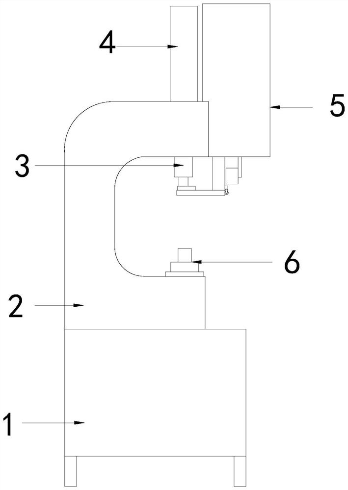
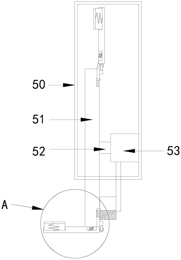
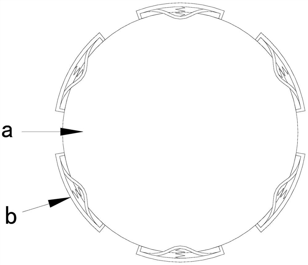
[0030] see Figure 1-6 , the present invention provides a technical scheme of hydraulic riveting machine: its structure includes a base 1, a C-shaped column 2, a riveting head 3, a lifting cylinder 4, a cleaning structure 5, and a positioning fixture 6, and the base 1 is welded with a C-shaped Column 2, the bottom of the C-shaped column 2 is provided with a positioning fixture 6, the riveting head 3 is arranged above the positioning fixture 6 and connected to the C-shaped column 2, and the top of the C-shaped column 2 is equipped with a lifting cylinder 4, The lifting cylinder 4 is connected to the riveting head 3, and the cleaning structure 5 is connected to the top side of the C-shaped column 2. The cleaning structure 5 includes a housing 50, a rotating body 51, a rotating shaft 52, and a motor 53. The housing A motor 53 is connected inside the body 50, and the motor 53 is connected with the rotating body 51 through a rotating shaft 52. The rotating body 51 includes a turnta...

Embodiment 2

[0033] see Figure 1-8 , the present invention provides a technical scheme of hydraulic riveting machine: its structure includes a base 1, a C-shaped column 2, a riveting head 3, a lifting cylinder 4, a cleaning structure 5, and a positioning fixture 6, and the base 1 is welded with a C-shaped Column 2, the bottom of the C-shaped column 2 is provided with a positioning fixture 6, the riveting head 3 is arranged above the positioning fixture 6 and connected to the C-shaped column 2, and the top of the C-shaped column 2 is equipped with a lifting cylinder 4, The lifting cylinder 4 is connected to the riveting head 3, and the cleaning structure 5 is connected to the top side of the C-shaped column 2. The cleaning structure 5 includes a housing 50, a rotating body 51, a rotating shaft 52, and a motor 53. The housing A motor 53 is connected inside the body 50, and the motor 53 is connected with the rotating body 51 through a rotating shaft 52. The rotating body 51 includes a turnta...


PUM


Abstract

The invention discloses a hydraulic riveting machine. The hydraulic riveting machine structurally comprises a base, a C-shaped column, a riveting head, a lifting oil cylinder, a cleaning structure anda positioning clamp, wherein the C-shaped column is welded to the base; the positioning clamp is arranged at the bottom of the C-shaped column; the riveting head is arranged above the positioning clamp and connected to the C-shaped column; the lifting oil cylinder is installed at the top of the C-shaped column and connected with the riveting head; and the cleaning structure is connected to the side surface of the top of the C-shaped column, the cleaning structure comprises a shell, a rotating body, a rotating shaft and a motor, the interior of the shell is connected with the motor, and the motor is connected with the rotating body through the rotating shaft. The riveting machine has the beneficial effects that the riveting head can be wiped through a rotary wiping part, so that the bonding phenomenon is avoided, the riveting quality is guaranteed, automatic wiping can be carried out, manual operation is not needed, and omission is avoided.

Description

technical field [0001] The invention relates to the field of riveting machines, in particular to a hydraulic riveting machine. Background technique [0002] The hydraulic riveting machine uses the hydraulic stamping machine equipment and the special connection die to go through a momentary high-pressure processing process, and according to the cold extrusion deformation of the plate itself, a stress-free internal mosaic point with a certain tensile and shear strength is formed. , two or more layers of boards of different materials and different thicknesses can be connected. [0003] When the hydraulic riveting machine is used, the riveting head will slightly bond when processing some materials, which will affect the quality of the next riveting, and it needs to be manually cleaned regularly, which is troublesome, and manual operation is prone to omissions. Contents of the invention [0004] The main purpose of the present invention is to overcome the deficiencies of the p...

Claims


Application Information

Patent Timeline
Patent Type & Authority Applications(China)
IPC IPC(8): B21J15/38B21J15/10B08B1/04
CPCB08B1/006B08B1/04B21J15/10B21J15/38
Inventor 姜志写
Owner 姜志写
Why Eureka
Try Eureka