Compensated Finger Chuck
A chuck and claw technology, applied in the field of compensating finger-press chucks, can solve problems such as workpiece deformation and achieve the effect of reducing deformation
- Summary
- Abstract
- Description
- Claims
- Application Information
AI Technical Summary
Problems solved by technology
Method used
Image
Examples
Embodiment 1
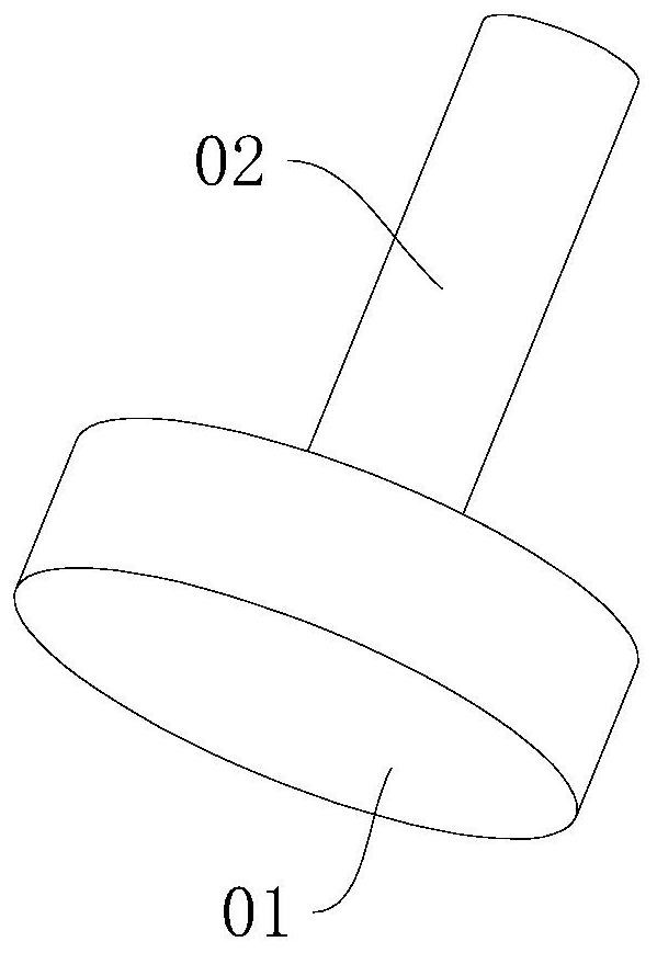
[0051] refer to figure 1 , the disc workpiece includes a disc body 01 and a shaft body 02 .
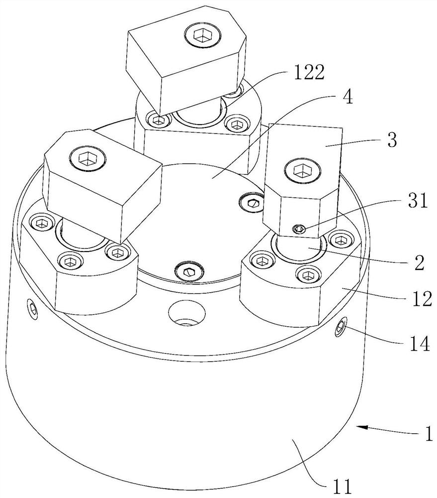
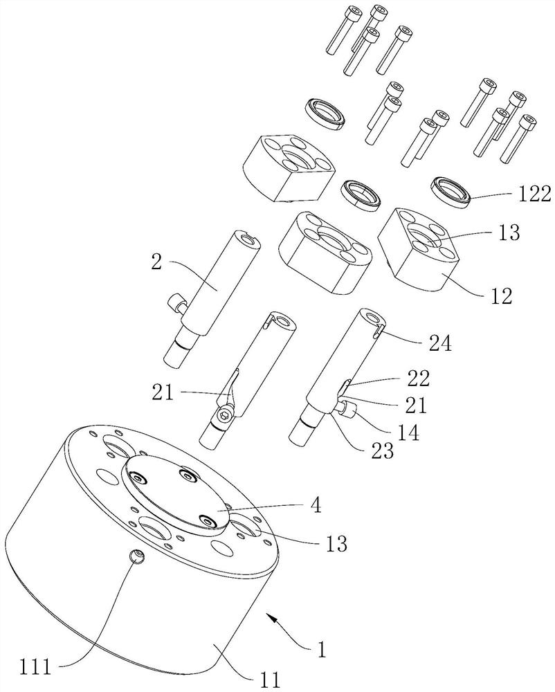
[0052] refer to figure 2, The compensation type finger-press chuck includes a base 1 , a pull rod 2 and jaws 3 . The base 1 is cylindrical as a whole; there are three tie rods 2 parallel to the axis of the base 1, and the three are arranged at intervals along the circumference of the base 1. Rotate around its own axis; one end of the pull rod 2 protrudes from the base 1, and there are three corresponding claws 3, and one claw 3 is fixedly connected to the end of a pull rod 2 protruding from the base 1, and makes one end of the claw 3 along the pull rod The radial direction of 2 protrudes from the outer periphery of pull rod 2.
[0053] refer to figure 1 , 2 , the base 1 is also provided with a positioning piece 4, and the positioning piece 4 is located between the three pull rods 2. When working, the workpiece is placed on the positioning piece 4, and the end surface of the disc...
Embodiment 2
[0073] refer to Figure 9 , the disc-like workpiece includes a bump 03 , a disc body 01 and a shaft body 02 arranged in sequence along its axial direction.
[0074] The differences between this embodiment and Embodiment 1 are:
[0075] refer to Figure 9 , 10 , three bolts pass through the positioning member 4 and are connected to the seat body 11 to realize the detachable connection between the positioning member 4 and the seat body 11 . The end of the positioning member 4 facing away from the seat body 11 is provided with a positioning groove 41, the positioning groove 41 is adapted to the bump 03, that is, the circumferential side wall of the positioning groove 41 is attached to the outer periphery of the bump 03, and the disc body 01 is away from the shaft body When the end surface of 02 abuts against the end surface of the positioning member 4 , there is a gap between the groove bottom of the positioning groove 41 and the protrusion 03 .
[0076] The implementation pr...
PUM
 Abstract
Description
Claims
Application Information
 - R&D
- Intellectual Property
- Life Sciences
- Materials
- Tech Scout
- Unparalleled Data Quality
- Higher Quality Content
- 60% Fewer Hallucinations
Browse by: Latest US Patents, China's latest patents, Technical Efficacy Thesaurus, Application Domain, Technology Topic, Popular Technical Reports.
© 2025 PatSnap. All rights reserved.Legal|Privacy policy|Modern Slavery Act Transparency Statement|Sitemap|About US| Contact US: help@patsnap.com


