
Numerical control lathe auxiliary heat dissipation device capable of automatically adjusting spraying speed of cooling liquid

A technology for CNC lathes and auxiliary heat dissipation, which is applied in metal processing machinery parts, maintenance and safety accessories, metal processing equipment, etc. The effect of automatic adjustment, ensuring personnel safety, and reducing consumption

Inactive Publication Date: 2021-01-05
杭州悟伦机械科技有限公司
View PDF0 Cites 6 Cited by
  • Summary
  • Abstract
  • Description
  • Claims
  • Application Information

AI Technical Summary

Problems solved by technology

[0002] Most of the current CNC lathes achieve the purpose of cooling by spraying coolant on the workpiece being processed. The requirements are constantly changing, and the resulting temperature is also changing accordingly. At this time, there is a certain danger in manually adjusting the spraying speed of the coolant, and it also interferes with the normal operation of the lathe. If the coolant is directly adjusted to the maximum value will also cause greater waste

Method used


Image

  • Numerical control lathe auxiliary heat dissipation device capable of automatically adjusting spraying speed of cooling liquid
  • Numerical control lathe auxiliary heat dissipation device capable of automatically adjusting spraying speed of cooling liquid
  • Numerical control lathe auxiliary heat dissipation device capable of automatically adjusting spraying speed of cooling liquid

Examples


Embodiment Construction

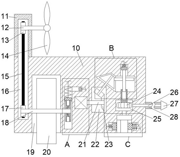
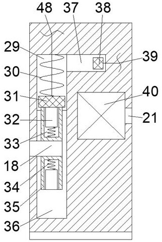
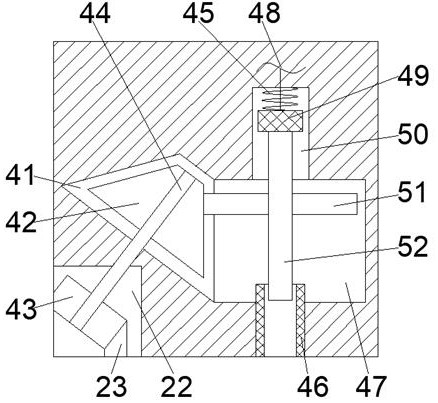
[0016] Combine below Figure 1-4 The present invention is described in detail, wherein, for the convenience of description, the orientations mentioned below are defined as follows: figure 1 The up, down, left, right, front and back directions of the projection relationship itself are the same.

[0017] An auxiliary cooling device for a CNC lathe that can automatically adjust the cooling liquid spray speed described in conjunction with accompanying drawings 1-4, includes a main body box 10, and a wind wheel box 11 is fixedly connected to the left end of the upper end surface of the main body box 10, and the The wind wheel box 11 is provided with a wind wheel transmission belt cavity 16 extending downwards into the main body box 10, and the right side of the wind wheel transmission belt cavity 16 is provided with a turntable friction wheel located in the main body box 10 and opening downward. Cavity 19, the right side of the turntable friction wheel cavity 19 is provided with a...


PUM


Abstract

The invention relates to the related field of numerical control lathe heat dissipation equipment, and discloses a numerical control lathe auxiliary heat dissipation device capable of automatically adjusting spraying speed of cooling liquid. The numerical control lathe auxiliary heat dissipation device comprises a main body box, wherein a wind wheel box is fixedly connected to the tail end of the left side of the upper end face of the main body box, a wind wheel transmission belt cavity extending downwards into the main body box is formed in the wind wheel box, and a rotating disc friction wheel cavity which is located in the main body box and is provided with a downward opening is formed in the right side of the wind wheel transmission belt cavity. According to the device, the purpose of monitoring the turning machining rotating speed in real time is achieved through a rotating disc friction wheel abutting against a numerical control lathe rotating chuck, meanwhile, the spraying speedof the cooling liquid can be correspondingly changed in cooperation with the speed adjusting effect of a speed adjusting cavity, and therefore full-automatic adjustment of the cooling liquid is achieved, the personnel safety is guaranteed, and meanwhile the use amount of the cooling liquid is more reasonably reduced; and when the machining rotating speed is too high, the purpose of automatically switching the efficient cooling liquid when the rotating speed is too high is achieved through a triggering magnetic block and switching of a main sliding block valve and an auxiliary sliding block valve, and therefore the machining quality of workpieces is guaranteed.

Description

technical field [0001] The invention relates to the related field of heat dissipation equipment for numerically controlled machine tools, in particular to an auxiliary heat dissipation device for numerically controlled lathes that can automatically adjust the spraying speed of coolant. Background technique [0002] Most of the current CNC lathes achieve the purpose of cooling by spraying coolant on the workpiece being processed. The requirements are constantly changing, and the resulting temperature is also changing accordingly. At this time, there is a certain danger in manually adjusting the spraying speed of the coolant, and it also interferes with the normal operation of the lathe. If the coolant is directly adjusted to the maximum Value will also cause greater waste. Contents of the invention [0003] The object of the present invention is to provide an auxiliary heat dissipation device for a numerically controlled lathe that can automatically adjust the cooling liqu...

Claims


Application Information

Patent Timeline
IPC IPC(8): B23Q11/10
CPCB23Q11/10
Inventor 赵羽
Owner 杭州悟伦机械科技有限公司
Learn More