Automatic blocky workpiece conveying mechanism

A technology for automatic conveying and workpieces, applied in conveyors, conveyor objects, conveyor control devices, etc., can solve the problems of time-consuming and laborious, low efficiency, manual loading and unloading cannot meet industrial needs, etc., to achieve convenient operation and improve work efficiency. Efficient, compact effect

Pending Publication Date: 2021-01-05
JIANGSU COLLEGE OF INFORMATION TECH
View PDF0 Cites 1 Cited by
  • Summary
  • Abstract
  • Description
  • Claims
  • Application Information

AI Technical Summary

Problems solved by technology

[0003] In the prior art, the commonly used method of conveying massive workpieces is manual operation, which is time-consuming, laborious, and inefficient. In mass production, manual loading and unloading can no longer meet industrial needs.

Method used


Image

  • Automatic blocky workpiece conveying mechanism
  • Automatic blocky workpiece conveying mechanism
  • Automatic blocky workpiece conveying mechanism

Examples


Embodiment Construction

[0022] The specific implementation manner of the present invention will be described below in conjunction with the accompanying drawings.

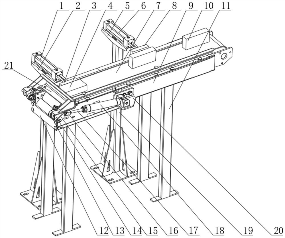
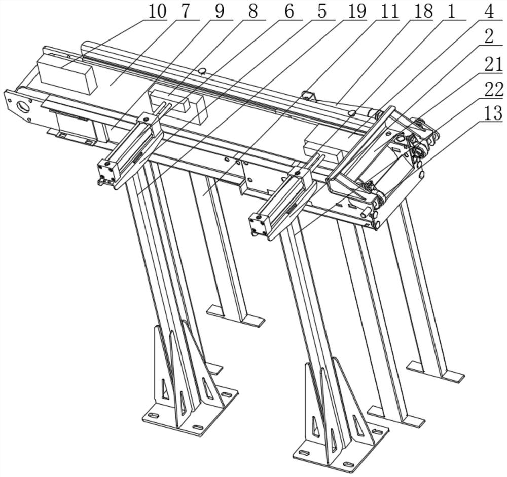
[0023] Such as figure 1 , figure 2 and image 3 As shown, the block-shaped workpiece automatic conveying mechanism of the present embodiment includes side plates 9 arranged at intervals and symmetrically, and a conveyor belt 7 is installed between the two side plates 9, and the conveyor belt 7 is driven by a driving device. The bottom is supported by supporting legs 11; the No. 1 fixed platform 5 and the No. 2 fixed platform 2 with intervals are arranged on the side of the conveyor belt 7, the No. 1 cylinder 6 is installed on the No. 1 fixed platform 5, and the output end of the No. 1 cylinder 6 is fixed with a No. 1 Push block 8, No. 1 photoelectric sensor is installed on the side plate 9 corresponding to No. 1 cylinder 6, No. 2 cylinder 1 is installed on No. 2 fixed platform 2, and No. No. 2 photoelectric sensor is installed on the c...


PUM


Abstract

The invention relates to an automatic blocky workpiece conveying mechanism. The automatic blocky workpiece conveying mechanism comprises side plates which are symmetrically arranged at intervals, wherein a conveying belt is mounted between the two side plates; the conveying belt is driven to work by a driving device; the bottoms of the side plates are supported by support legs; a first fixing platform and a second fixing platform which are spaced are arranged beside the conveying belt; a first cylinder is mounted on the first fixing platform; a first pushing block is fixed to the output end ofthe first cylinder; a first photoelectric sensor is mounted on a side plate corresponding to the first cylinder; a second cylinder is mounted on the second fixing platform; a first pushing block is fixed to the output end of the second cylinder; a second photoelectric sensor is mounted on the side plate corresponding to the second cylinder; a right-angle plate is fixed to the outer side of one side plate; a third cylinder is fixed to the right-angle plate; a connector is fixed to the head of a piston rod of the third cylinder; the connector is hinged with a connecting rod; a blanking baffle is mounted at the head of the connecting rod through a rotating shaft. The automatic blocky workpiece conveying mechanism is high in working efficiency.

Description

technical field [0001] The invention relates to the technical field of automatic conveying mechanisms, in particular to an automatic conveying mechanism for block workpieces. Background technique [0002] When blanking a block workpiece, because the block may be placed flat or sideways, according to actual work requirements, the final blanking needs to be laid flat for subsequent processing. [0003] In the prior art, the commonly used method of conveying massive workpieces is manual operation, which is time-consuming, laborious, and inefficient. In mass production, manual loading and unloading can no longer meet industrial needs. Contents of the invention [0004] The applicant aims at the above-mentioned shortcomings in the existing production technology, and provides an automatic conveying mechanism for block-shaped workpieces, so that the automatic conveying of block-shaped workpieces can be conveniently completed, and each block-shaped workpiece can be placed flat whe...

Claims


Application Information

Patent Timeline
Patent Type & Authority Applications(China)
IPC IPC(8): B65G15/30B65G21/20B65G41/00B65G47/88B65G47/82B65G47/22B65G43/08
CPCB65G15/30B65G21/2063B65G41/00B65G43/08B65G47/22B65G47/82B65G47/8815B65G2203/044
Inventor 项亚南喻永康
Owner JIANGSU COLLEGE OF INFORMATION TECH
Why Eureka
Try Eureka