
Integrated device for winding and taking up of textiles

A technology of winding and threading rollers, applied in the textile field, can solve the problems of easy loosening of yarns when taking up, and achieve the effect of improving quality, avoiding loosening of yarns, and avoiding loosening of take-ups.

Pending Publication Date: 2021-01-05
ZHEJIANG MEILAIYA TEXTILE
View PDF9 Cites 1 Cited by
  • Summary
  • Abstract
  • Description
  • Claims
  • Application Information

AI Technical Summary

Problems solved by technology

[0004] Aiming at the deficiencies of the prior art, the present invention provides an integrated device for textile winding and take-up, which solves the problem that the yarn take-up is easy to loose

Method used


Image

  • Integrated device for winding and taking up of textiles
  • Integrated device for winding and taking up of textiles
  • Integrated device for winding and taking up of textiles

Examples


Embodiment 1

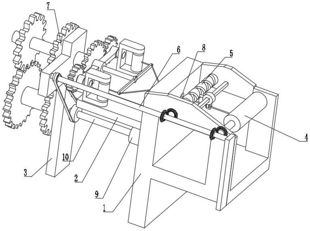
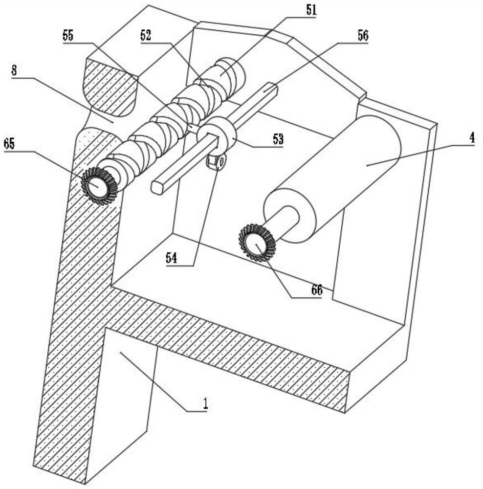
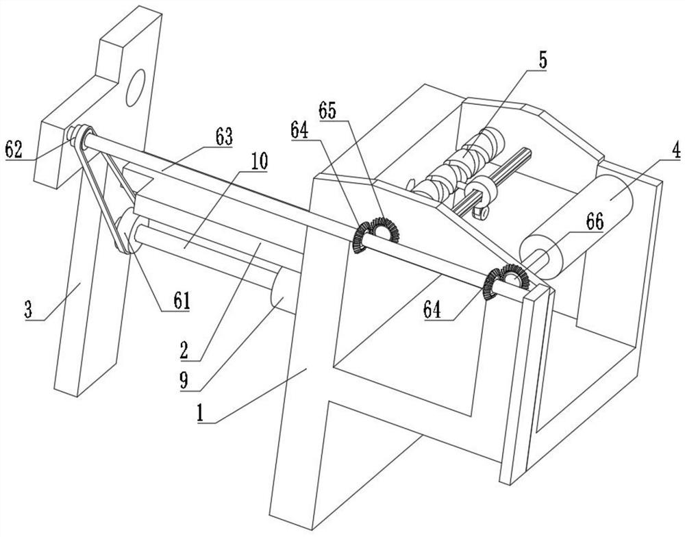
[0029] see Figure 1-5 , an integrated device for textile winding and take-up, comprising a fixed base 1, the left side of the fixed base 1 is respectively fixedly connected with a connecting plate 2 and a motor 9, the motor 9 is located under the connecting plate 2, and the left side of the connecting plate 2 is fixed Connected with a support plate 3, the interior of the support plate 3 is provided with a transmission mechanism 7, the output end of the motor 9 is fixedly connected with a transmission shaft 10, the surface of the transmission shaft 10 is provided with a connection mechanism 6, and the inner wall of the fixed seat 1 is rotatably connected with a take-up wire The roller 4 is provided with a wire mechanism 5 inside the fixed seat 1 , and a threading hole 8 is opened inside the fixed seat 1 .

[0030] In this embodiment, the guide wire mechanism 5 includes a rotating roller 51, the surface of the rotating roller 51 is provided with a turning groove 52, the inner w...

Embodiment 2

[0035] see Figure 6-7, the transmission mechanism 7 includes a first gear set 71, the right side of the first gear set 71 is fixedly connected with the left end of the transmission shaft 10, the surface of the first gear set 71 is engaged with a gear one 72 and a second gear set 73 respectively, the gears A connecting sleeve 77 is fixedly connected to the shaft center of -72, and the surface of the connecting sleeve 77 is connected to the inside of the second gear set 73 for rotation, and the surface of the second gear set 73 is connected to the inside of the support plate 3 for rotation, and the second gear set 73 The surface meshing with gear two 76, through the design of two gear sets, the rotation speed of gear two 76 and the rotation of the second gear set 73 has a certain speed difference, which improves the tightness in the winding process and avoids excessive speed and uncompact winding.

[0036] In this embodiment, the inside of the connecting sleeve 77 is fixedly co...


PUM


Abstract

The invention relates to the technical field of textile, and discloses an integrated device for winding and taking up of textiles. The integrated device comprises a fixing seat, wherein the left sideof the fixing seat is fixedly connected with a connecting plate and a motor respectively; the motor is located below the connecting plate; the left side of the connecting plate is fixedly connected with a supporting plate; a transmission mechanism is arranged inside the supporting plate; the output end of the motor is fixedly connected with a transmission shaft; a connecting mechanism is arrangedon the surface of the transmission shaft; a take-up roller is rotationally connected to the inner wall of the fixing seat; and a wire guide mechanism is arranged inside the fixing seat. According to the integrated device for winding and taking up of the textiles, the operation of the motor is controlled, a connecting rod is driven to rotate through the transmission of a belt so that a rotating roller can rotate to drive a sliding sleeve to circularly move back and forth by utilizing a rotating groove on the surface of the rotating roller, then a wound yarn is driven to move back and forth to be uniformly wound on the surface of the take-up roller, and thus the yarn loosening and take-up loosening can be well avoided.

Description

technical field [0001] The invention relates to the technical field of textiles, in particular to an integrated textile winding and winding device. Background technique [0002] The original meaning of textile is taken from the general term of spinning and weaving, but with the continuous development and improvement of the textile knowledge system and subject system, especially after the emergence of non-woven textile materials and three-dimensional composite weaving technologies, it is not only the traditional hand spinning And weaving, also including non-woven fabric technology, modern three-dimensional weaving technology, modern electrostatic nano-netting technology and other clothing, industrial and decorative textiles. [0003] At present, in the process of weaving, some textile yarns need to be thickened by winding to weave yarns of different diameters. The existing technology is very easy in the process of winding. It is easy to have thread take-up confusion, resulti...

Claims


Application Information

Patent Timeline
IPC IPC(8): B65H54/553B65H54/44B65H54/30B65H54/70B65H54/04B65H51/015
CPCB65H54/553B65H54/44B65H54/30B65H54/70B65H54/04B65H51/015B65H2701/31
Inventor 王楠睿王荣军
Owner ZHEJIANG MEILAIYA TEXTILE
Learn More