Textile thread positioning device of textile machine

A positioning device and textile thread technology, which is applied in the directions of transportation and packaging, conveying filamentous materials, and thin material processing, etc., can solve the problems of winding and winding of textile threads, and achieve reduced friction, reduced quantity, and reduced cost input Effect

Inactive Publication Date: 2021-01-05
ZHEJIANG MEILAIYA TEXTILE
View PDF11 Cites 2 Cited by
  • Summary
  • Abstract
  • Description
  • Claims
  • Application Information

AI Technical Summary

Problems solved by technology

[0004] Aiming at the deficiencies of the prior art, the present invention provides a textile thread positioning device for a textile machine, which solves the problem of entanglement of the textile thread when it is taken up

Method used


Image

  • Textile thread positioning device of textile machine
  • Textile thread positioning device of textile machine
  • Textile thread positioning device of textile machine

Examples


Embodiment 1

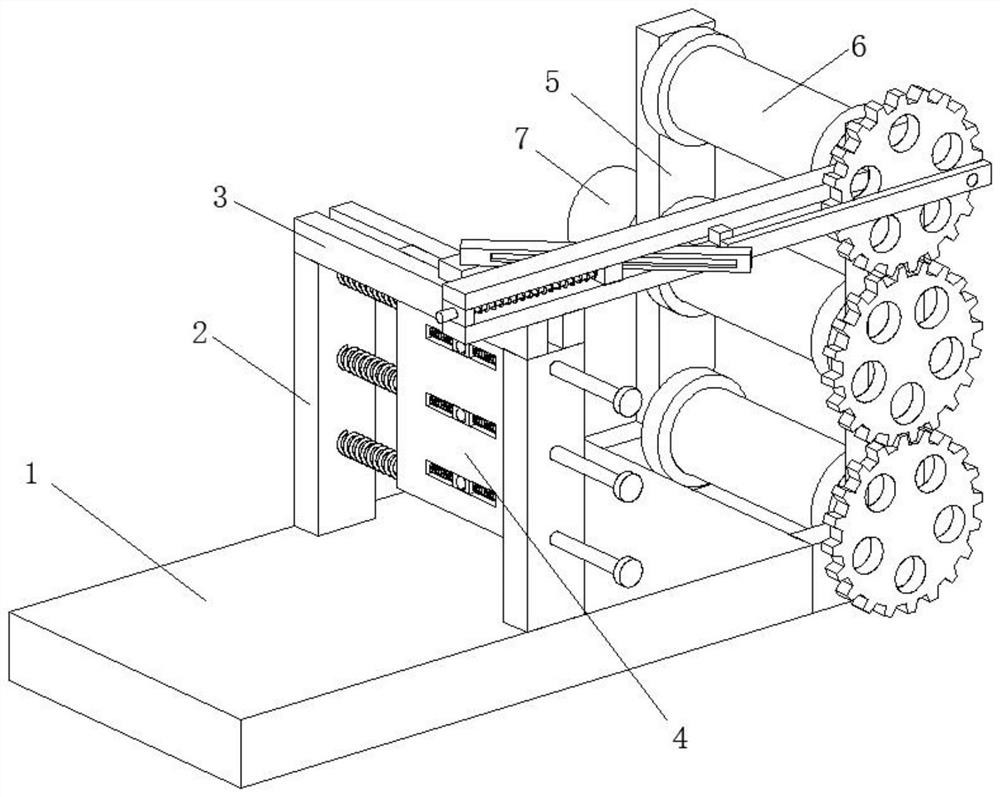
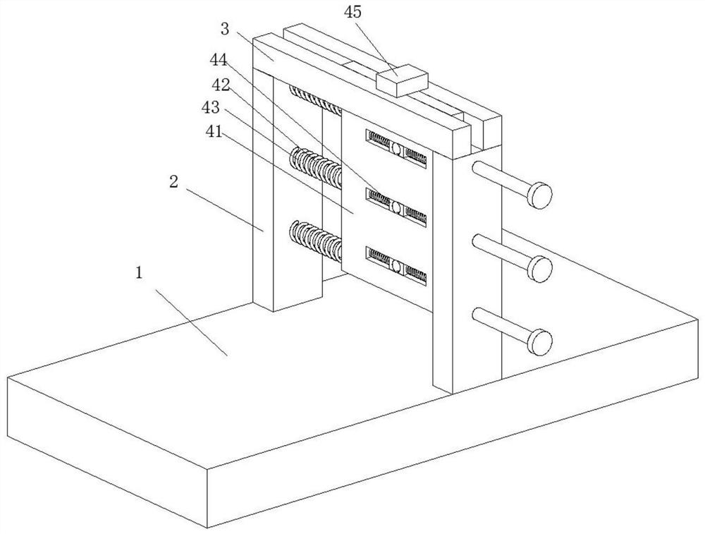
[0034] A textile thread positioning device for a textile machine, such as Figure 1-Figure 8 As shown, including workbench 1, two support plates 2 are vertically welded on workbench 1, two baffle plates 3 are respectively welded on the top of support plate 2, positioning mechanism 4 is arranged between two support plates 2, the working Two support columns 5 are respectively welded at the rear of the table 1, and a winding mechanism 6 is arranged between the two support columns 5, and a motor 7 is connected to the left side of the support column 5 through bolts; a motor 7 can drive the textile thread at the same time Rewinding can drive the positioning mechanism 4 to position the wire, thereby reducing the number of motors 7 placed, thereby reducing cost input and maximizing benefits.

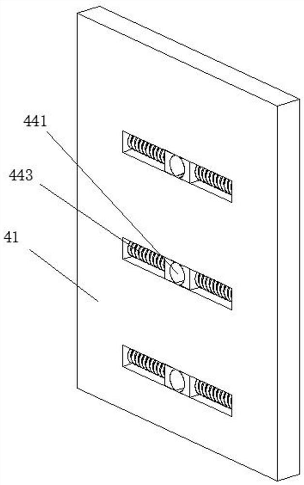
[0035] In this embodiment, the positioning mechanism 4 includes a moving plate 41, the two sides of the moving plate 41 are welded with guide rods 42, the surface of the guide rod 42 is sleeved ...

Embodiment 2

[0041] Such as Figure 7-Figure 10 As shown, the left side of the connection block 67 is slidably connected with the inwall of the fixed rod 65, the front portion of the connection block 67 is movably connected with the rear portion of the push rod 612, the rear portion of the slide plate 68 is movably connected with the inwall of the push rod 612, and the guide post The surface of 69 is slidingly connected with the inner wall of fixed rod 65, and the two ends of No. 2 spring 611 are in contact with the front portion of slide plate 68 and the inner wall of fixed rod 65 respectively, and the lower surface of push rod 612 is connected with the upper surface of slide block 45 in rotation , the lower surface of the fixed rod 65 is welded and fixed with the upper surface of the baffle plate 3, the connecting block 67 and the push rod 612 can rotate and slide, so that the connecting block 67 can push the push rod 612 to rotate with linear motion, and the slide plate 68 and the push r...


PUM


Abstract

The invention relates to the technical field of textile machines, and discloses a textile thread positioning device of a textile machine. The textile thread positioning device comprises a workbench, two support plates are correspondingly welded at the top of the workbench, two baffle plates are correspondingly welded at the tops of the support plates, a positioning mechanism is arranged between the two support plates, two supporting columns are welded to the rear portion of the workbench, a winding mechanism is arranged between the two supporting columns, and a motor is connected to the left sides of the supporting columns through bolts. Through cooperative work of the positioning mechanism and a transmission mechanism, threads can be separated for winding, the situation that the device cannot continue to work due to intertwining of the textile threads during winding can be prevented due to the fact that the threads are wound left and right repeatedly, friction borne by the textile threads in the winding process can be reduced through a guide device, the risk of breakage of the textile threads during winding is reduced, and the quality of the textile threads after winding of the textile threads is greatly improved.

Description

technical field [0001] The invention relates to the technical field of textile machines, in particular to a textile thread positioning device for a textile machine. Background technique [0002] Textile machine, also known as textile machine, loom, cotton spinning machine, etc., the ancient textile machine is a loom driven by manpower. The textile machine is the full name of the tool that processes raw materials such as thread, silk, and hemp into silk and then weaves them into cloth. Such as spinning pendants, spinning wheels, spindles, pedal looms, modern mechanical looms, modern numerically controlled automatic looms, etc. [0003] At present, the textile machines in the market do not have a positioning device for the textile thread when the thread is taken up at the end, and it is easy to cause the textile thread to be entangled when the thread is taken up, resulting in the inability to continue the winding operation of the textile thread. Therefore, a textile thread pos...

Claims


Application Information

Patent Timeline
Patent Type & Authority Applications(China)
IPC IPC(8): B65H54/553B65H54/42B65H54/70B65H67/04
CPCB65H54/553B65H54/42B65H54/70B65H67/0411B65H67/0417B65H2701/31B65H2301/417
Inventor 朱恬
Owner ZHEJIANG MEILAIYA TEXTILE
Why Eureka
Try Eureka