
Labyrinth type magnetic liquid sealing device

A magnetic liquid and sealing device technology, which is applied in the direction of engine sealing, engine components, mechanical equipment, etc., can solve the problems of increasing the volume of the sealing device, large leakage, and increasing the axial length of the sealing device, so as to increase the flow path , improve sealing, improve the effect of safety

Active Publication Date: 2021-01-05
TSINGHUA UNIV
View PDF10 Cites 4 Cited by
  • Summary
  • Abstract
  • Description
  • Claims
  • Application Information

AI Technical Summary

Problems solved by technology

However, once the magnetic liquid seal fails, its leakage will be large, which will reduce the safety of the magnetic liquid seal.
[0003] The labyrinth magnetic liquid sealing device in the related art uses a labyrinth seal structure processed on the inner ring of the permanent magnet. However, this method has poor processing performance due to the brittleness and hardness of the magnet. Another labyrinth magnetic liquid sealing device in the related art The device uses a labyrinth seal on the inner ring of the permanent magnet. However, the labyrinth seal is a straight-through type, and the leakage reduction effect is not good. Moreover, this method increases the axial length of the sealing device and increases the volume of the sealing device.

Method used


Image

  • Labyrinth type magnetic liquid sealing device
  • Labyrinth type magnetic liquid sealing device

Examples


Embodiment Construction

[0028] The following describes in detail the embodiments of the present invention, examples of which are illustrated in the accompanying drawings. The embodiments described below by referring to the figures are exemplary and are intended to explain the present invention and should not be construed as limiting the present invention.

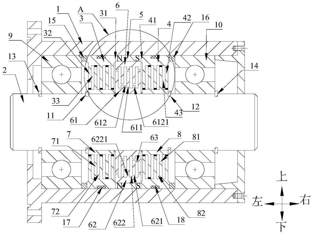
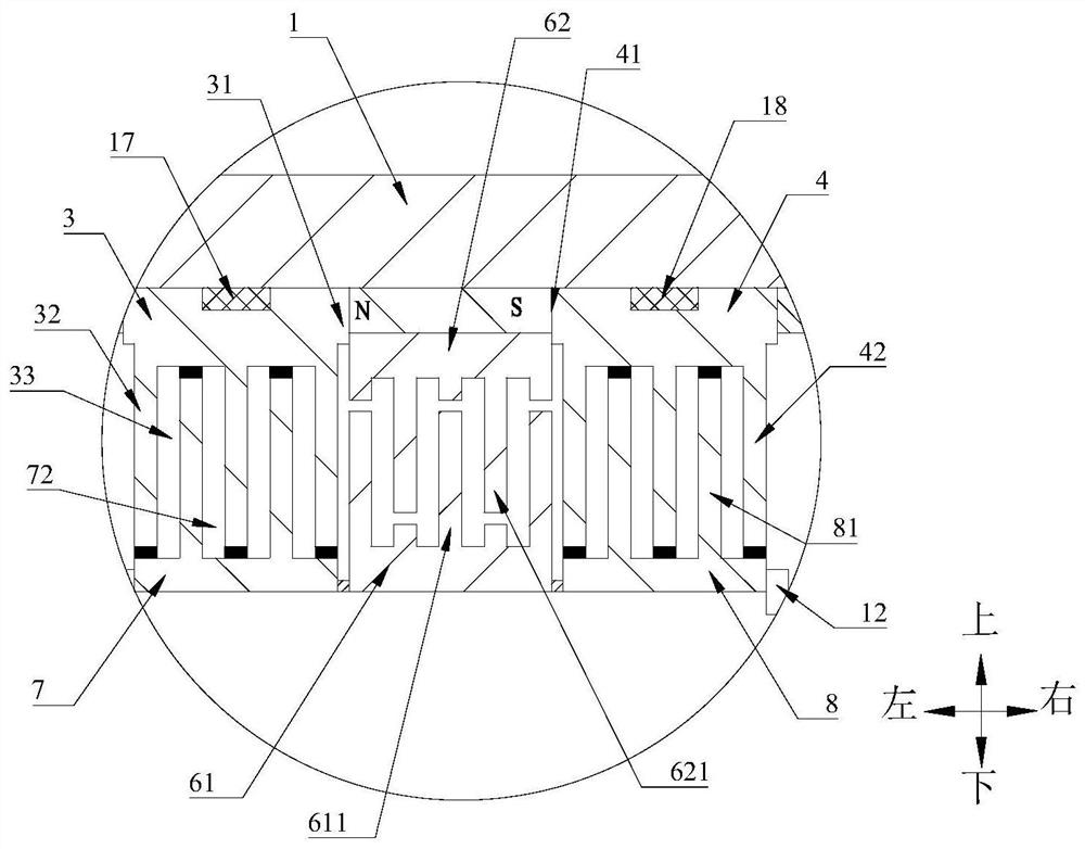
[0029] The labyrinth magnetic liquid sealing device according to the embodiment of the present invention includes a housing 1, a rotating shaft 2, a first pole piece 3, a second pole piece 4, a permanent magnet 5, a labyrinth seal 6, a first shaft sleeve 7 and a second shaft Set of 8.

[0030] The housing 1 has a chamber inside. like figure 1 As shown, the left end of the casing 1 is provided with a flange part, and the flange part is provided with a plurality of threaded holes, and the flange part is suitable for connecting with external equipment.

[0031] The rotating shaft 2 is rotatably arranged in the chamber. like figure 1 As shown, th...


PUM


Abstract

The invention discloses a labyrinth type magnetic liquid sealing device which comprises a shell, a rotating shaft, a first pole shoe, a second pole shoe, a permanent magnet and a labyrinth sealing piece. A cavity is formed in the shell, and the rotating shaft is rotationally arranged in the cavity. The first pole shoe and the second pole shoe are arranged on the rotating shaft in a sleeving mannerand arranged in the axial direction of the rotating shaft in a spaced manner, the permanent magnet surrounds the rotating shaft and is located between the first pole shoe and the second pole shoe, the labyrinth sealing piece is arranged between the first pole shoe and the second pole shoe, and the outer circumferential face of the labyrinth sealing piece makes contact with the inner circumferential face of the permanent magnet. A first gap is formed between the labyrinth sealing piece and the first pole shoe in the axial direction of the rotating shaft, a second gap is formed between the labyrinth sealing piece and the second pole shoe in the axial direction of the rotating shaft, and a bent and extended flow channel communicating with the first gap and the second gap is formed in the labyrinth sealing piece. The labyrinth type magnetic liquid sealing device also has the sealing capacity when the magnetic liquid fails, and the safety is improved.

Description

technical field [0001] The invention belongs to the technical field of liquid sealing, and in particular relates to a labyrinth magnetic liquid sealing device. Background technique [0002] Magnetic liquid seals are widely used due to their advantages of zero leakage, long life, and low friction. However, once the magnetic liquid seal fails, its leakage will be large, which will reduce the safety of the magnetic liquid seal. [0003] The labyrinth magnetic liquid sealing device in the related art uses a labyrinth seal structure processed on the inner ring of the permanent magnet. However, this method has poor processing performance due to the brittleness and hardness of the magnet. Another labyrinth magnetic liquid sealing device in the related art The device uses a labyrinth seal on the inner ring of the permanent magnet. However, the labyrinth seal is a straight-through type, and the leakage reduction effect is not good. Moreover, this method increases the axial length of...

Claims


Application Information

Patent Timeline
IPC IPC(8): F16J15/43F16J15/447
CPCF16J15/43F16J15/4472
Inventor 李德才杨晟赵云翔陈诺
Owner TSINGHUA UNIV
Learn More