Self-regulating conveying and smearing device for automobile parts
A regular technology for auto parts, applied in conveyors, transportation and packaging, engine components, etc., can solve problems such as poor lubrication effect, uneven lubrication, and low lubrication efficiency
- Summary
- Abstract
- Description
- Claims
- Application Information
AI Technical Summary
Problems solved by technology
Method used
Image
Examples
Embodiment 1
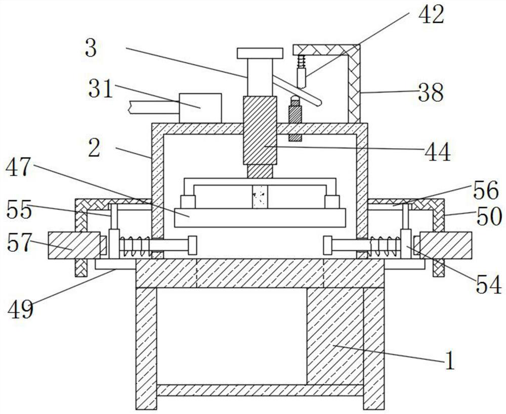
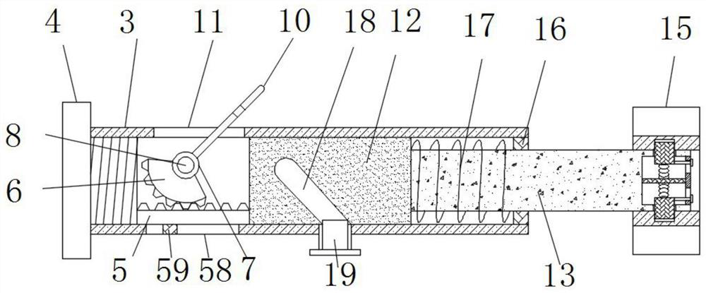
[0034] see Figure 1-10 According to an embodiment of the present invention, a self-aligning conveying and coating device for auto parts includes a conveyor belt device 1. The conveyor belt device 1 is composed of an existing conveyor belt, a transmission assembly, a motor and a frame body, and will not be described too much. The top of the conveyor belt device 1 is fixedly connected with a fixed frame 2, and the shape design of the fixed frame 2 is similar to a U shape. The top of the fixed frame 2 is fixedly connected with a plurality of sleeves 3, and the top of the sleeve 3 is threaded. Closing cover 4, the inside of the sleeve 3 is provided with a tooth plate 5, and the sleeve 3 is provided with a limit chute 3 58 near the tooth plate 5, and a limit slide 58 is provided in the limit chute 3 58 Block three 59, the three limit sliders 59 are fixedly connected with the tooth plate 5, the cooperation of the three limit slide blocks 59 and the three limit chute 58 can make the...
Embodiment 2
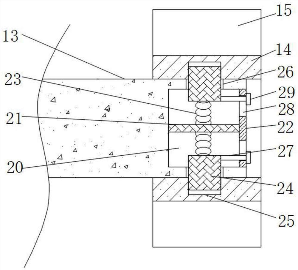
[0039] see Figure 2-3 , the connecting mechanism includes a groove 20, a connecting plate one 21, a connecting plate two 22, a spring two 23, a fixed block 24, a fixed groove 25 and a through hole 26, and the connecting rod one 13 is far away from one end of the movable block 12 There is a groove 20, the center of the groove 20 is fixedly connected with a connecting plate 21, and the port of the groove 20 is fixedly connected with a connecting plate 2 22, and the side wall of the groove 20 has a plurality of through holes. Hole 26, the through hole 26 communicates with the outside world, and is evenly distributed at the port of the connecting rod one 13, the connecting plate one 21 is connected with the fixed block 24 through the spring two 23, the inner wall of the connecting ring 14 is close to the connecting rod one. There is a fixing groove 25 at the hole 26, and the port of the fixing block 24 passes through the through hole 26 and is located in the fixing groove 25, and...
Embodiment 3
[0041] see Figure 5-6 , the oiling mechanism includes an annular oil tank 30 and a pump 31, the bottom end of the sleeve 3 is fixedly connected with the annular oil tank 30, the connecting rod 13 runs through the middle part of the annular oil tank 30, and the fixed frame 2 The top of the pump is fixedly connected with a pump 31, the output end of the pump 31 is connected to the annular oil tank 30 through a pipeline, the fixed frame 2 is provided with a hole that allows the pipeline to pass through, and the input end of the pump 31 is connected to the corresponding The oil storage tank is connected to facilitate the refueling operation of the annular oil tank 30. The bottom of the annular oil tank 30 is provided with an oil outlet mechanism that matches the connecting ring 14. The purpose of oiling the wiping cotton 15 can be achieved through the oiling mechanism. Described oil outlet mechanism comprises movable rod one 32, limit ring 33, spring three 34, connecting block 35...
PUM
 Abstract
Description
Claims
Application Information
 - R&D
- Intellectual Property
- Life Sciences
- Materials
- Tech Scout
- Unparalleled Data Quality
- Higher Quality Content
- 60% Fewer Hallucinations
Browse by: Latest US Patents, China's latest patents, Technical Efficacy Thesaurus, Application Domain, Technology Topic, Popular Technical Reports.
© 2025 PatSnap. All rights reserved.Legal|Privacy policy|Modern Slavery Act Transparency Statement|Sitemap|About US| Contact US: help@patsnap.com


