
Recoil-free firearm applied to unmanned aerial vehicle

A technology of recoil and drones, applied in the field of firearms, can solve problems affecting the flight stability of drones, and achieve the effects of stable operation, reasonable structural design, flexible and reliable operation

Pending Publication Date: 2021-01-05
马梓淇
View PDF1 Cites 0 Cited by
  • Summary
  • Abstract
  • Description
  • Claims
  • Application Information

AI Technical Summary

Problems solved by technology

[0005] In order to solve the problem that the recoil generated by firearms affects the flight stability of unmanned aerial vehicles, the present invention provides a recoilless firearm applied to unmanned aerial vehicles, which can realize the stable firing of firearms and ensure the flight of unmanned aerial vehicles stability

Method used


Image

  • Recoil-free firearm applied to unmanned aerial vehicle
  • Recoil-free firearm applied to unmanned aerial vehicle
  • Recoil-free firearm applied to unmanned aerial vehicle

Examples


Embodiment 1

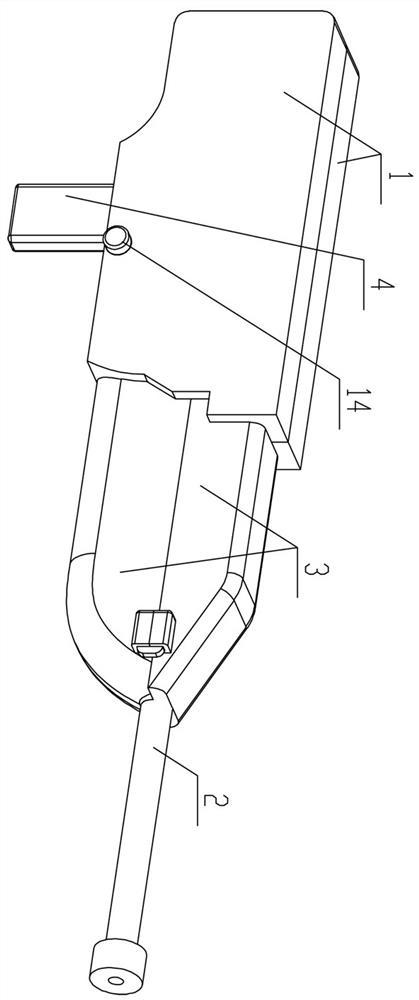
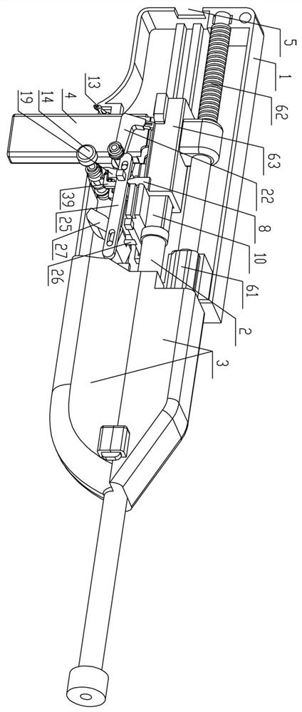
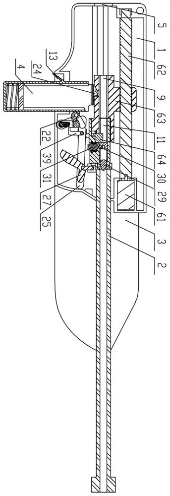
[0043] Such as Figure 1~Figure 9 As shown, a recoilless firearm applied to unmanned aerial vehicles includes a hollow gun shell 1 that is fastened and connected on both sides, a trigger mechanism placed between the gun shells 1 on both sides, a push mechanism, a firing pin mechanism, A gun barrel 2, a gun stock 3 and a magazine 4, the gun stock 3 is provided at the head end of the gun shell 1, and a rectangular sliding hole 5 is provided at the tail end of the gun shell 1;

[0044] The magazine 4 is arranged below the gun casing 1, and a driving lever 13 is arranged to rotate between the gun casings 1 on both sides. The magazine 4 and the gun case 1 are installed or removed from the gun case 1. The gun stock 3 is a split structure, and the gun stock 3 is fastened up and down on the gun barrel 2. The gun stock 3 and the gun case 1 One end of the gun barrel 2 is placed in the gun casing 1, and the other end passes through the gun stock 3 and is placed outside the gun casing 1....

Embodiment 2

[0075] On the basis of the first embodiment above, the trigger mechanism of this implementation is as follows: Figure 10 ~ Figure 11 As shown, the trigger mechanism includes a vertical barrel 33, a rack 34 elastically sliding with the vertical barrel 33, and a hammer motor 35. The vertical barrel 33 is vertically arranged on one side of the gun casing 1, and the side of the vertical barrel 33 is open. , the vertical cylinder 33 is elastically slidably connected with a sliding block through a compression spring, and the sliding block protrudes through the opening of the vertical cylinder 33 and is connected with the rack 34;

[0076] The rack 34 is vertically distributed, and the upper part of the rack 34 is provided with a second hammer 36, which corresponds to the position of the primer 30;

[0077]The hammer motor 35 is inserted between the gun casings 1 on both sides, and the hammer motor 35 is provided with an incomplete gear 37, and the incomplete gear 37 cooperates with...


PUM


Abstract

The invention relates to a recoil-free firearm applied to an unmanned aerial vehicle which comprises hollow gun shells, a triggering mechanism, a bullet pushing mechanism, a firing pin mechanism, a gun barrel, a gun stock and a magazine, the two sides of each hollow gun shell are connected in a buckled mode, the triggering mechanism is arranged between the gun shells on the two sides, and rectangular sliding holes are formed in the tail ends of the gun shells; the bullet pushing mechanism comprises a main motor, a screw connected with the main motor, a clamping base and a baffle elastically connected to the clamping base in a sliding mode, and a second rectangular smoothbore is formed in the clamping base; the firing pin mechanism comprises a fixing base and a firing pin assembly, a firstrectangular smooth-bore and a stepped groove which are communicated up and down are formed in the fixing base, and bullets are arranged in the first smooth-bore; and the gun barrel, the first smooth-bore, the second smooth-bore and the sliding holes are positioned on the same straight line and are sequentially communicated with one another. By improving the structure of the firearm, the recoil problem of a traditional firearm is solved, the stability of the firearm during firing is guaranteed, the influence on flight of the unmanned aerial vehicle is avoided, and the firearm can be well applied to combination of the unmanned aerial vehicle and the firearm.

Description

technical field [0001] The invention relates to the technical field of firearms, in particular to a recoilless firearm applied to unmanned aerial vehicles. Background technique [0002] With the development of UAV technology, UAVs are widely used in many fields. In order to meet people's needs for the diversification of UAV functions, the corresponding functional parts are usually mounted under the fuselage when UAVs are manufactured. , taking the combination of firearms and drones as an example, the biggest problem facing the combination is that the recoil force generated when the guns are fired affects the flight stability of the drone. [0003] Existing firearms are fired by manually pulling the trigger, the spring and the firing pin hit the primer of the bullet, and after the gunpowder in the bullet case ignites, the bullet head breaks away from the shell case and shoots out from the gun chamber, and the bullet case will hit the firing pin, thereby producing a certain re...

Claims


Application Information

Patent Timeline
Patent Type & Authority Applications(China)
IPC IPC(8): F41A19/06F41A19/13F41A19/42
CPCF41A19/06F41A19/13F41A19/42Y02T50/40
Inventor 马梓淇
Owner 马梓淇
Learn More