
Frequency locking system of multi-longitudinal-mode high-spectral-resolution laser radar interferometer

A laser radar and multi-longitudinal mode technology, applied in radio wave measurement systems, instruments, electromagnetic wave re-radiation, etc., can solve the problems of high temperature accuracy and poor short-term stability, and achieve low external environment requirements and low cost The effect of low cost and simple equipment

Pending Publication Date: 2021-01-05
ZHEJIANG UNIV
View PDF0 Cites 0 Cited by
  • Summary
  • Abstract
  • Description
  • Claims
  • Application Information

AI Technical Summary

Problems solved by technology

Although this method can achieve long-term frequency stability, the slow-response temperature adjustment method is destined to have poor short-term stability and requires extremely high temperature accuracy. Therefore, a new frequency-locking method is required to make all longitudinal modes The atmospheric echo signal strictly matches the frequency discrimination curve of the device
However, the multi-longitudinal mode laser in the multi-longitudinal mode HSRL has a simple structure and directly outputs pulsed laser light from the resonator, so the conventional continuous laser frequency locking method is no longer applicable in this system

Method used


Image

  • Frequency locking system of multi-longitudinal-mode high-spectral-resolution laser radar interferometer
  • Frequency locking system of multi-longitudinal-mode high-spectral-resolution laser radar interferometer
  • Frequency locking system of multi-longitudinal-mode high-spectral-resolution laser radar interferometer

Examples


Embodiment Construction

[0028] The present invention will be further described in detail below with reference to the accompanying drawings and embodiments. It should be noted that the following embodiments are intended to facilitate the understanding of the present invention, but do not limit it in any way.

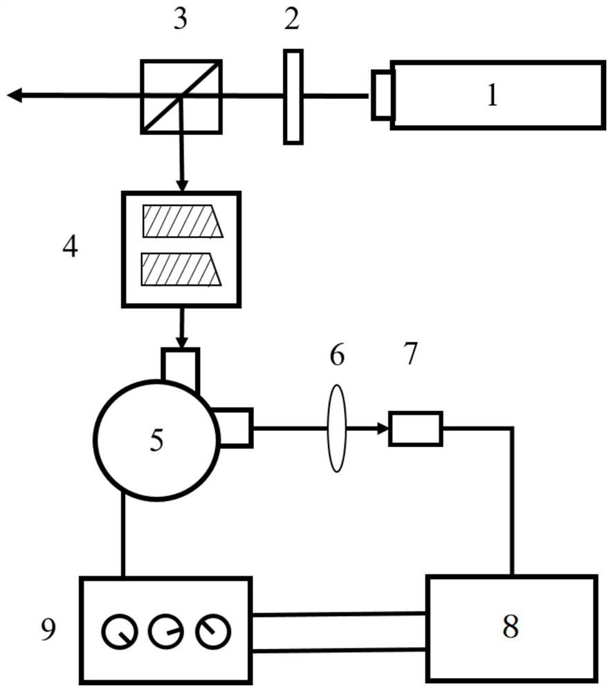
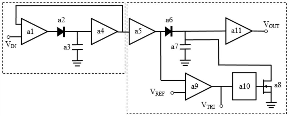
[0029] like figure 1 As shown, a multi-longitudinal-mode high-spectral-resolution laser radar interferometer frequency-locking system includes a multi-longitudinal-mode laser 1, a half-wave plate 2, a polarization beam splitter 3, an acousto-optic modulation module 4, and a spectral frequency discrimination interferometer 5, Converging lens 6, photodetector 7, peak hold circuit 8, proportional-integral-differential servo control module 9.

[0030] The laser output from the multi-longitudinal mode laser 1 is firstly polarized by a half-wave plate 2 , and then a beam of light is split by a polarization beam splitter 3 to enter an acousto-optic modulation module 4 . The frequency-locked light is f...


PUM


Abstract

The invention discloses a frequency locking system of a multi-longitudinal-mode high-spectral-resolution laser radar interferometer. The frequency locking system comprises a multi-longitudinal-mode laser, a half-wave plate, a polarization splitting prism, an acousto-optic modulation module, a spectrum frequency discrimination interferometer, a converging lens, a photoelectric detector, a peak holding circuit and a proportional-integral-differential servo control module, multi-longitudinal-mode pulse laser output by the multi-longitudinal-mode laser passes through the half-wave plate and the polarization splitting prism and then is split to obtain a low-power light beam. The low-power light speed is subjected to frequency shift by the acousto-optic modulation module and then enters the spectrum frequency discrimination interferometer, and the emitted light passes through the converging lens and then is received by the photoelectric detector; and after an electric signal output by the photoelectric detector is transmitted to the peak holding circuit to be processed, the electric signal is output to the proportional-integral-differential servo control module, and a tuning voltage is output to act on the spectrum frequency discrimination interferometer to achieve resonant frequency locking. According to the invention, the requirement of the multi-longitudinal-mode HSRL on the frequency stability of the spectrum frequency discrimination interferometer can be met.

Description

technical field [0001] The invention belongs to the technical field of atmospheric laser radar, in particular to a multi-longitudinal-mode high-spectral resolution laser radar interferometer frequency locking system based on a peak hold circuit. Background technique [0002] High Spectral Resolution Liar (High Spectral Resolution Liar, HSRL) is currently one of the most accurate atmospheric aerosol detection systems, and its advantage lies in the use of filters with high spectral resolution to detect atmospheric The aerosol meter scattering signal is separated from the atmospheric molecule Rayleigh scattering signal, so that the backscattering coefficient and extinction coefficient of the aerosol can be accurately inverted. [0003] In this context, considering the poor adaptability to the environment and the bulky factors of the single longitudinal mode laser used in HSRL, the research on a new HSRL system using multi-longitudinal mode lasers is ongoing. The principle of m...

Claims


Application Information

Patent Timeline
Patent Type & Authority Applications(China)
IPC IPC(8): G01S17/88G01S17/89G01S7/4861G01S7/486G01S7/484G01S7/481G01S7/48
CPCG01S17/88G01S17/89G01S7/481G01S7/484G01S7/486G01S7/4861G01S7/4802Y02A90/10
Inventor 刘东陈非同刘崇王彬宇王南朝
Owner ZHEJIANG UNIV
Learn More