Process for controlling smelting silicon content of low-silicon steel

A technology of silicon content and low silicon steel is applied in the low silicon steel smelting silicon content control process, the low silicon variety steel prevents silicon increase in the smelting process and stably controls the silicon content of the molten steel end point, and can solve the problem of poor slag blocking in tapping and casting blanks. , change the judgment and other issues, to achieve the effect of improving the hit rate of the end component, improving economic benefits and reducing production costs

Active Publication Date: 2012-09-19
NANJING IRON & STEEL CO LTD
View PDF3 Cites 22 Cited by
  • Summary
  • Abstract
  • Description
  • Claims
  • Application Information

AI Technical Summary

Problems solved by technology

[0002] Since the silicon element in the steel has an important influence on the coating performance of the steel plate, it is generally believed that when the [Si] in the steel exceeds 0.04%, the oxide film formed on the surface of the high-temperature coating original plate is difficult to be fully restored, and a thick oxide film is formed on the surface after coating. Off-white coating with poor adhesion
At present, the silicon content in molten steel at the end of converter blowing is basically traces ([Si]﹤0.001%), and the content of (Si02) in converter slag is between 10% and 20%. 1. A certain amount of silicon is inevitably brought into the ferroalloy, resulting in the enrichment of silicon content in the top slag of the ladle. During the subsequent deoxidation of molten steel, slagging, desulfurization and removal of inclusions, the (Si02) in the top slag of the ladle is easily reduced by a strong reducing agent such as aluminum. [Si] enters the molten steel, causing silicon increase in molten steel, which makes the deoxidation, desulfurization, slagging inclusion control of molten steel and silicon increase phenomenon contradictory during the production of low silicon steel, preventing silicon increase in the entire smelting process from becoming the smelting low silicon variety steel. bottleneck
In order to break through this restrictive bottleneck link, it is an urgent problem to develop a control process to prevent silicon increase in the smelting process and stabilize the silicon content at the end of continuous casting, especially for continuous multi-heat casting of low-silicon steel with a silicon content of less than 0.03%. , there will be a series of problems such as broken pouring and slab change judgment due to unstable silicon content control

Method used


Image

  • Process for controlling smelting silicon content of low-silicon steel
  • Process for controlling smelting silicon content of low-silicon steel

Examples


Embodiment 1

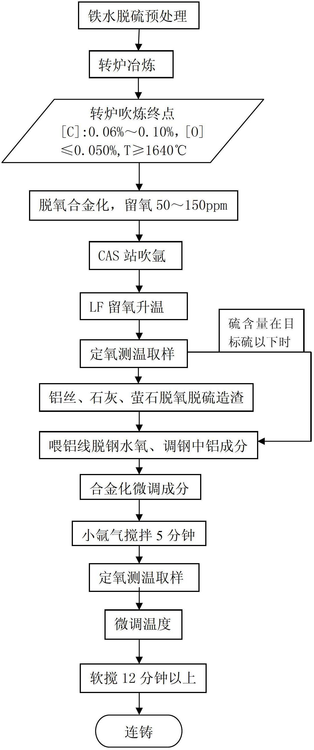
[0022] The low-silicon steel smelting silicon content control technological process of the present embodiment is as follows figure 1 shown, including:

[0023] Converter smelting process:

[0024] ①Deep desulphurization operation: The incoming molten iron is pretreated by desulfurization and cleaned of slag, requiring [S]0.002%; controlling impurities in scrap steel, reducing sulfur content in converter steel, reducing the desulfurization burden of LF process to create strong reduction slag, and preventing strong reduction Atmosphere, long-time refining and other factors reduce the silicon in the top slag of the ladle, causing the molten steel to return to silicon;

[0025] ②End point operation: improve the hit rate of one-time carbon drawing, avoid point blowing, prevent molten steel from overoxidation, control the oxygen in the steel by controlling the carbon at the end point of the converter, and improve the tapping of the converter as much as possible under the condition ...

Embodiment 2

[0034] The low-silicon steel smelting silicon content control technological process of the present embodiment is as follows figure 1 shown, including:

[0035] Converter smelting process:

[0036] ①Deep desulphurization operation: The incoming molten iron is pretreated by desulfurization and cleaned of slag, requiring [S] 0.0015%; control impurities in scrap steel, reduce sulfur content in converter steel, reduce the desulfurization burden of LF process to create strong reduction slag, and prevent strong reduction Atmosphere, long-time refining and other factors reduce the silicon in the top slag of the ladle, causing the molten steel to return to silicon;

[0037] ②End point operation: improve the hit rate of one-time carbon drawing, avoid point blowing, prevent molten steel from overoxidation, control the oxygen in the steel by controlling the carbon at the end point of the converter, and improve the tapping of the converter as much as possible under the condition of satisf...

Embodiment 3

[0046] The low-silicon steel smelting silicon content control technological process of the present embodiment is as follows figure 1 shown, including:

[0047] Converter smelting process:

[0048] ①Deep desulphurization operation: The incoming molten iron is pretreated by desulfurization and cleaned of slag, requiring [S] 0.001%; ​​controlling impurities in scrap steel, reducing sulfur content in converter steel, reducing the desulfurization burden of LF process to create strong reduction slag, and preventing strong reduction Atmosphere, long-time refining and other factors reduce the silicon in the top slag of the ladle, causing the molten steel to return to silicon;

[0049] ②End point operation: improve the hit rate of one-time carbon drawing, avoid point blowing, prevent molten steel from overoxidation, control the oxygen in the steel by controlling the carbon at the end point of the converter, and improve the tapping of the converter as much as possible under the conditi...


PUM


Abstract

The invention belongs to a steel-making process in the metallurgy field and relates to a process for preventing silicon increase in the smelting process of low-silicon steel and stably controlling silicon content at an end point of molten steel. By means of accurate ingredient and temperature control at a blowing end point of converter, steel-tapping deoxidization alloying and remaining oxygen operation, temperature rise of oxidizing slag at an earlier stage of a refining furnace and optimization of a slagging process in deoxidization desulfuration procedures, molten steel increase (Si) in the whole smelting process is smaller than 0.02%, the ingredient control at a smelting end point is stable and accurate, surfaces of casting blank and inside quality are excellent, the substandard rate of the casting blanks is reduced, and the economic profit is improved.

Description

technical field [0001] The invention belongs to the steelmaking process in the field of metallurgy, and relates to a process for controlling silicon content in low-silicon steel smelting, in particular to a process for preventing silicon increase in the smelting process and stably controlling the silicon content at the end point of molten steel for low-silicon variety steel. Background technique [0002] Since the silicon element in the steel has an important influence on the coating performance of the steel plate, it is generally believed that when the [Si] in the steel exceeds 0.04%, the oxide film formed on the surface of the high-temperature coating original plate is difficult to be fully restored, and a thick oxide film is formed on the surface after coating. Off-white coating with poor adhesion. At present, the silicon content in molten steel at the end of converter blowing is basically traces ([Si]﹤0.001%), and the content of (Si02) in converter slag is between 10% an...

Claims


Application Information

Patent Timeline
Patent Type & Authority Applications(China)
IPC IPC(8): C21C5/30C21C7/00
Inventor 蔡可森王攀峰周桂成孟令东陈德胜吴国平王永瑞
Owner NANJING IRON & STEEL CO LTD
Why Eureka
Try Eureka