Touch control positioning method and device and terminal equipment
A technology of touch positioning and touch points, which is applied in the direction of instruments, electrical digital data processing, and input/output process of data processing, etc., to achieve the effect of improving accuracy, improving convenience, and reducing hardware costs
- Summary
- Abstract
- Description
- Claims
- Application Information
AI Technical Summary
Problems solved by technology
Method used
Image
Examples
Embodiment 1
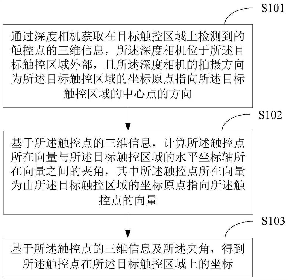
[0036] figure 1 A schematic flow chart of the first touch positioning method provided by the embodiment of the present application is shown, and the details are as follows:
[0037] In S101, the three-dimensional information of the touch point detected on the target touch area is obtained by using a depth camera, the depth camera is located outside the target touch area, and the shooting direction of the depth camera is the target touch point The coordinate origin of the control area points to the direction of the center point of the target touch area.
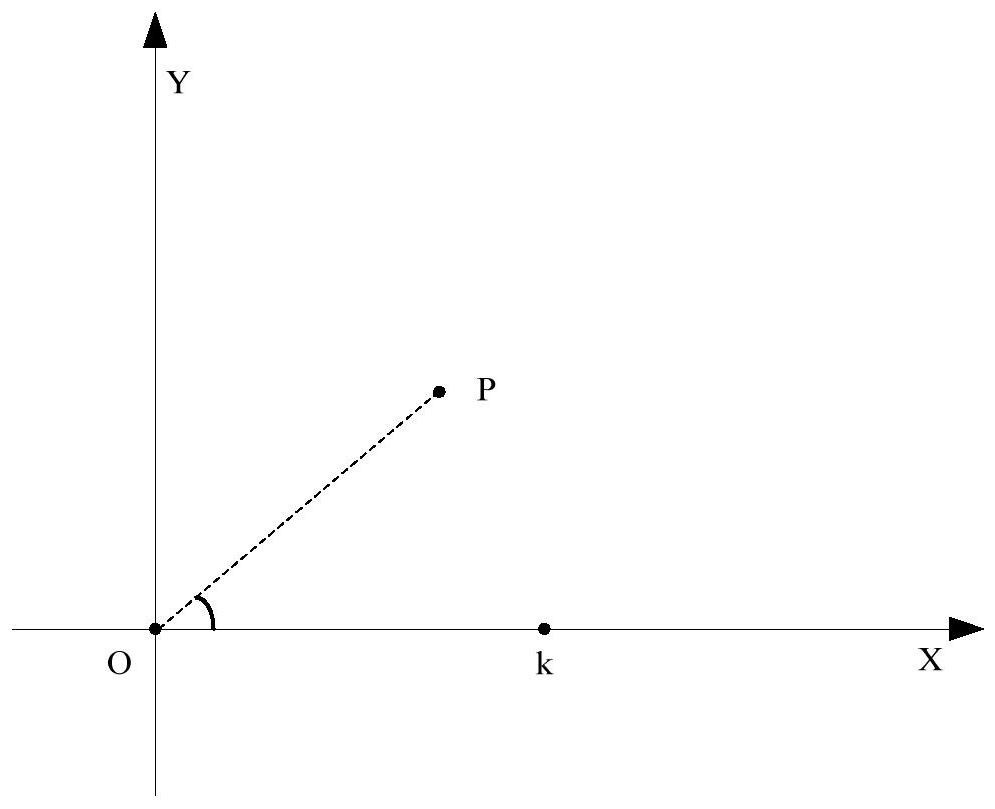
[0038] The target touch area is the area that receives touch operations (click and swipe operations by the user), and the target touch area can be the screen of a designated terminal device (such as a computer, TV, mobile phone, etc.), an LED electronic display, a billboard, etc. , the outer surface of a glass cabinet, a projection screen, a projection wall, or a surface area on any material object such as a wooden board, the...
Embodiment 2
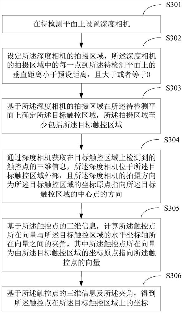
[0062] image 3 A schematic flowchart of the second touch positioning method provided by the embodiment of the present application is shown, and the details are as follows:
[0063] In S301, a depth camera is set on a plane to be detected.
[0064] The plane to be detected is the plane on the specified target object, for example, the screen of terminal equipment (such as computer, TV, mobile phone, etc.), LED electronic display, billboard, glass cabinet, projection screen, projection wall or wood, etc. The plane of the outer surface of the target object. A depth camera is set on the plane to be tested, so that the depth camera can capture touch points on the plane to be tested.
[0065] In S302, the shooting area of the depth camera is set, and the vertical distance from each point in the shooting area of the depth camera to the plane to be detected is less than a preset distance and greater than or equal to 0.
[0066] Set the shooting area of the depth camera. The v...
Embodiment 3
[0080] Figure 7 A schematic flow chart of the third touch positioning method provided by the embodiment of the present application is shown, and the details are as follows:
[0081] In S701, a depth camera is set on a plane to be detected.
[0082] S701 in this embodiment is the same as S301 in Embodiment 2. For details, please refer to the relevant description of S301 in Embodiment 2, which will not be repeated here.
[0083] In S702, the shooting area of the depth camera is set, and the vertical distance from each point in the shooting area of the depth camera to the plane to be detected is less than a preset distance and greater than or equal to 0.
[0084] S702 in this embodiment is the same as S302 in Embodiment 2. For details, please refer to the relevant description of S302 in Embodiment 2, which will not be repeated here.
[0085] Optionally, the setting the shooting area of the depth camera includes:
[0086] The shooting area is set by installing a lens cla...
PUM
 Abstract
Description
Claims
Application Information
 - R&D
- Intellectual Property
- Life Sciences
- Materials
- Tech Scout
- Unparalleled Data Quality
- Higher Quality Content
- 60% Fewer Hallucinations
Browse by: Latest US Patents, China's latest patents, Technical Efficacy Thesaurus, Application Domain, Technology Topic, Popular Technical Reports.
© 2025 PatSnap. All rights reserved.Legal|Privacy policy|Modern Slavery Act Transparency Statement|Sitemap|About US| Contact US: help@patsnap.com


