Eureka AIR delivers breakthrough ideas for toughest innovation challenges, trusted by R&D personnel around the world.

3D printing high-pressure rapid pressurizing device and energy-saving method

A 3D printing and pressurizing device technology, which is applied in manufacturing auxiliary devices, processing environment adjustment, additive processing, etc., can solve the problems of reduced printing efficiency, increased printing cost, waste of compressed air, etc., and achieves low printing cost and reduced energy consumption Effect of wasting and reducing pressurization time

Inactive Publication Date: 2021-01-08
SUZHOU ANHUI SAIERWODE INTERNET OF THINGS TECH CO LTD
View PDF2 Cites 0 Cited by
  • Summary
  • Abstract
  • Description
  • Claims
  • Application Information

AI Technical Summary

Problems solved by technology

[0002] The quality of 3D printing can be improved in a high-pressure environment, but it takes a long time to pressurize and inflate the high-pressure printing chamber, and a lot of compressed air needs to be exhausted to open the door, which will waste a lot of compressed air, and re-pressurize and inflate again after printing, which will reduce the printing efficiency and increase printing cost

Method used


Image

  • 3D printing high-pressure rapid pressurizing device and energy-saving method

Examples


Embodiment Construction

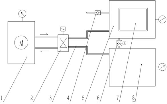
[0014] Such as figure 1 The 3D printing high-pressure rapid pressurization device shown includes an air compressor 1, a printing chamber 5, and an air storage tank 8. The air compressor 1 is connected to the printing chamber 5 and the air storage tank through a reversing valve 2 and a high-pressure air pipe 3, respectively. 8. The printing chamber 5 and the air storage tank 8 are connected by pipelines, the tank communication control valve 6 is set on the connecting pipeline, the chamber door 7 and the ventilation pipe are set on the printing chamber 5, and the one-way valve is set on the ventilation pipe 4. Set pressure sensors on the printing chamber 5 and the air storage tank 8, and the control unit connects the pressure sensor, the storage tank to the control valve 6 and the reversing valve 2, and connects the air compressor 1, the printing chamber 5, and the air storage tank 8 through the pipe The pipeline and the storage tank installed on the pipeline communicate with th...


PUM


Abstract

The invention provides a 3D printing high-pressure rapid pressurizing device which comprises an air compressor, a printing bin and an air storage tank. The air compressor is connected with the printing bin and the air storage tank through a reversing valve and a high-pressure air pipe, the printing bin and the air storage tank are connected through a pipeline, a bin tank communicating control valve is arranged on the connecting pipeline, and a bin door and a ventilation pipe are arranged on the printing bin. A one-way valve is arranged on the ventilation pipe, pressure sensors are arranged onthe printing bin and the air storage tank, a control unit is connected with the pressure sensors, the bin tank communicating control valve and the reversing valve, and the air compressor, the printingbin and the air storage tank form a circulation body through pipelines, the bin tank communicating control valve and the reversing valve, wherein the bin tank communicating control valve and the reversing valve are installed on the pipelines. Through a simple circulating device, the pressurizing time can be greatly shortened by adopting the method, energy waste is reduced, and the printing cost is low.

Description

technical field [0001] The invention relates to a 3D printing high-pressure fast pressurizing device and an energy-saving method, belonging to the technical field of 3D printing. Background technique [0002] The quality of 3D printing can be improved in a high-pressure environment, but it takes a long time to pressurize and inflate the high-pressure printing chamber, and a lot of compressed air needs to be exhausted to open the door, which will waste a lot of compressed air, and re-pressurize and inflate again after printing, which will reduce the printing efficiency and increase printing costs. Contents of the invention [0003] The purpose of the present invention is to solve the problems existing in the current technology, and provide a 3D printing high-pressure rapid pressurization device and an energy-saving method. [0004] In order to achieve the above purpose, the technical solution provided by the present invention is: a 3D printing high-pressure rapid pressuriz...

Claims


Application Information

Patent Timeline
IPC IPC(8): B29C64/364B29C64/20B33Y40/00B33Y30/00
CPCB29C64/364B29C64/20B33Y40/00B33Y30/00
Inventor 徐航
Owner SUZHOU ANHUI SAIERWODE INTERNET OF THINGS TECH CO LTD
Why Eureka
Eureka Blog
Learn More