
Rail equipment and detection method

A technology of equipment and track, which is applied in the field of track equipment and detection, can solve the problems that affect the intelligentization of robots, be susceptible to external interference, and affect the detection efficiency, and achieve the goal of measuring while moving the equipment, improving detection efficiency, and improving accuracy Effect

Active Publication Date: 2021-01-08
JD DIGITS HAIYI INFORMATION TECHNOLOGY CO LTD
View PDF12 Cites 7 Cited by
  • Summary
  • Abstract
  • Description
  • Claims
  • Application Information

AI Technical Summary

Problems solved by technology

[0004] In the prior art, a laser ranging device can be installed on the orbital robot, and the laser can be used to detect the distance between the rails, but this detection method is easily disturbed by the outside world, and the measurement is inaccurate; or the distance between the rails can be detected by using a single push rod. However, this detection method can only be detected when the robot is stopped, which greatly affects the detection efficiency and affects the intelligence of the robot.

Method used


Image

  • Rail equipment and detection method
  • Rail equipment and detection method
  • Rail equipment and detection method

Examples


Embodiment Construction

[0029] Hereinafter, embodiments of the present disclosure will be described with reference to the drawings. It should be understood, however, that these descriptions are exemplary only, and are not intended to limit the scope of the present disclosure. In the following detailed description, for purposes of explanation, numerous specific details are set forth in order to provide a thorough understanding of the embodiments of the present disclosure. It may be evident, however, that one or more embodiments may be practiced without these specific details. Also, in the following description, descriptions of well-known structures and techniques are omitted to avoid unnecessarily obscuring the concept of the present disclosure.

[0030] The terminology used herein is for the purpose of describing particular embodiments only, and is not intended to be limiting of the present disclosure. The terms "comprising", "comprising", etc. used herein indicate the presence of stated features, ...


PUM


Abstract

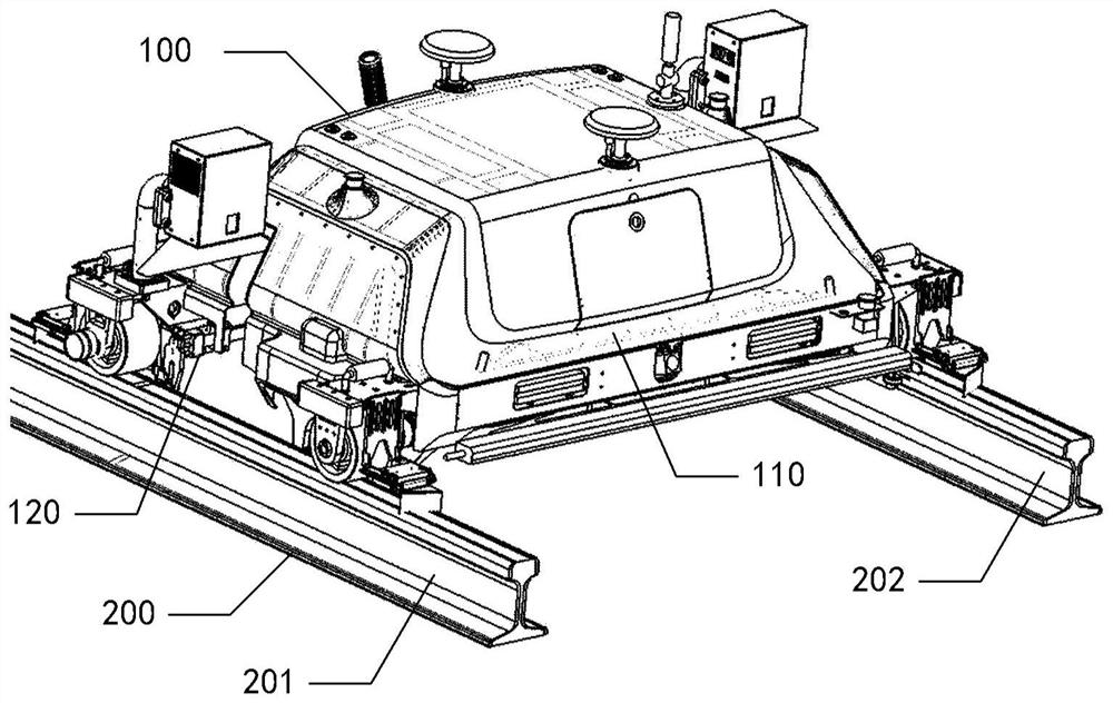
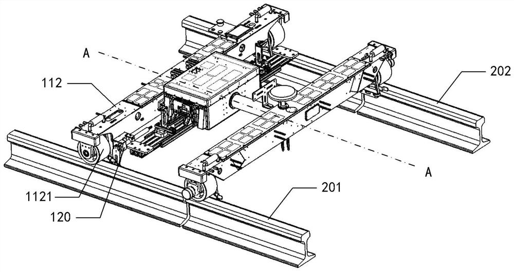
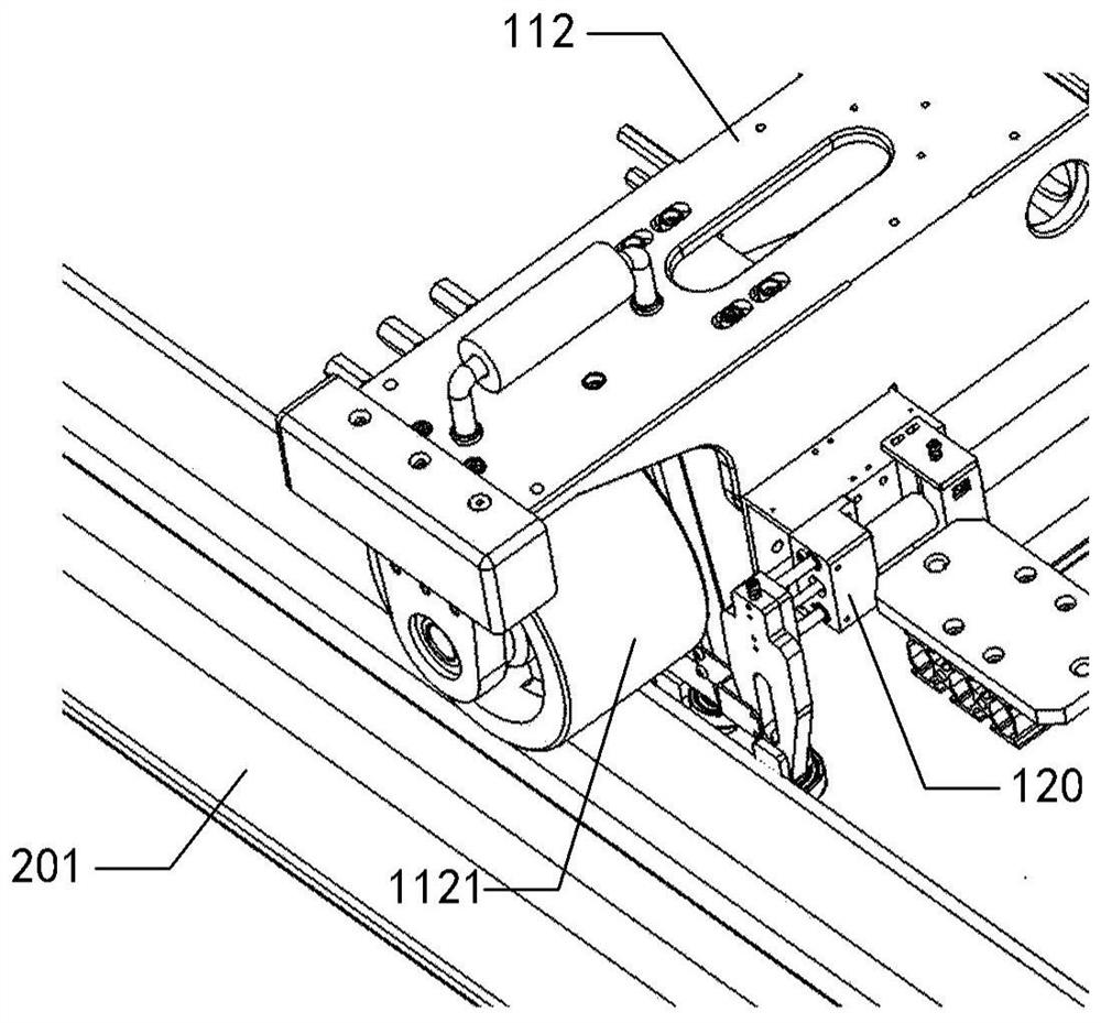
The invention provides rail equipment which comprises a body and at least one set of measuring device, and the body is used for being erected between two guide rails of a rail and moving along the rail; each group of measuring devices comprises two measuring devices which are respectively positioned in two side areas of the body; wherein the measuring device comprises a displacement sensor and a rolling piece, the displacement sensor comprises a shell and a rebound shaft, the shell is fixedly connected with the body, and the rebound shaft is configured to stretch out and draw back in the vertical direction of the advancing direction of the body relative to the shell; the rolling piece is used for making contact with the guide rail under the thrust of the rebound shaft and rolling relativeto the guide rail in the moving process of the body. The rolling pieces of the two measuring devices are used for making contact with the two guide rails respectively, and the displacement sensors ofthe two measuring devices are configured to detect the compression amount of the springback shafts of the two measuring devices so as to determine the relative positions of the body and the two guiderails and the rail distance between the two guide rails. The invention further provides a detection method.

Description

technical field [0001] The present disclosure relates to the technical field of track detection, and more particularly, to a track equipment and a detection method. Background technique [0002] Rails provide routes for vehicles and other equipment. They are widely used in the field of transportation, and can also be used in industrial production, logistics, and daily life where items or people need to be transported. After the track is laid, the track needs to be inspected, wherein the rail spacing between two parallel guide rails of the inspected track is one of the inspected contents. In order to improve the detection efficiency, a rail robot can be used to automatically detect the track. [0003] In the process of realizing the concept of the present disclosure, the inventors have found that at least the following problems exist in the related art: [0004] In the prior art, a laser ranging device can be installed on the orbital robot, and the laser can be used to dete...

Claims


Application Information

Patent Timeline
Patent Type & Authority Applications(China)
IPC IPC(8): B61K9/08G01B21/16
CPCB61K9/08G01B21/16
Inventor 姚秀军桂晨光程二亭
Owner JD DIGITS HAIYI INFORMATION TECHNOLOGY CO LTD
Learn More