Bionic joint type pneumatic bouncing leg

A bionic joint and pneumatic technology, applied in the field of bionic jumping robots, can solve the problems of failure to realize the jumping movement of large animals, poor controllability of dynamic parameters, insufficient controllable explosive force, etc., and achieve strong jumping ability, improved jumping ability, and reasonable structure Effect

Pending Publication Date: 2021-01-08
HARBIN INST OF TECH AT WEIHAI
View PDF0 Cites 1 Cited by
  • Summary
  • Abstract
  • Description
  • Claims
  • Application Information

AI Technical Summary

Problems solved by technology

In view of the insurmountable dynamic parameters of the pneumatic system, the controllability of the dynamic parameters is poor, and the existing single power source articulated jumping legs all use electric motors or hydraulic pressure with the aid of multiple elastic elements to improve the jumping explosive power, but they have not been able to achieve large animals due to insufficient controllable explosive power. horizontal jumping motion

Method used


Image

  • Bionic joint type pneumatic bouncing leg
  • Bionic joint type pneumatic bouncing leg

Examples


Embodiment Construction

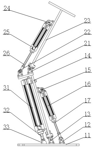
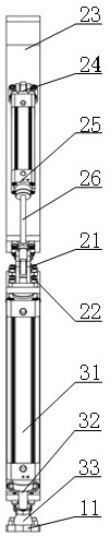
[0012] Depend on figure 1 It can be seen that a bionic joint type pneumatic bouncing leg includes an ankle joint, a knee joint and a pneumatic lower leg. It is characterized in that the ankle joint includes the foot 11 as the installation reference of each component and is in contact with the ground, and the rear ankle hinge support 12 and the front ankle hinge support 13 imitating the ankle joint of animals are respectively provided at the rear and middle. , the calf tibia 14 that rotates relative to the sole of the foot 11 around the front ankle hinge support 13, the ankle cylinder hinge support 15 that is fixedly connected to the calf tibia 14, and the ankle joint servo cylinder that rotates around the ankle cylinder hinge support 15 relative to the calf tibia 14 body 16, the ankle servo cylinder piston rod 17 that slides along the ankle joint servo cylinder cylinder 16 and rotates around the rear ankle hinge support 12 by means of pneumatic power; The rear knee hinge bear...


PUM


Abstract

The invention discloses a bionic joint type pneumatic bouncing leg which comprises an ankle joint, a knee joint and a pneumatic shank. Each of the ankle joint and the knee joint is a four-rod mechanism which is composed of three fixed-length rod pieces and a rod piece with the length adjusted through a servo air cylinder and adopts three hinges and a fixed connection part. A jumping servo air cylinder body of the pneumatic shank is fixedly connected with a shank tibia, and the ankle joint and the pneumatic shank are connected in parallel and then connected with the knee joint in series. Accurate control over the take-off direction and the landing posture of the bouncing leg is achieved by adjusting the bending angles of the ankle joint and the knee joint, and the jumping capacity of the bouncing leg is improved by driving the jumping servo air cylinder body, the ankle joints and the knee joints to move upwards together. Controllable landing buffering and posture stabilizing of the bouncing leg are achieved by adjusting the inflating and deflating processes of the ankle joint, the knee joint and the bouncing servo air cylinder. According to the bionic joint type pneumatic bouncing leg, pneumatic power integrating explosive power, controllability and self-buffering performance is used as a single power source, and the bionic joint type pneumatic bouncing leg is higher in bouncingcapacity.

Description

technical field [0001] The invention relates to the technical field of bionic jumping robots, in particular to a sagittal plane jumping bionic joint type pneumatic jumping leg which uses a servo cylinder to imitate animal leg muscles and ligaments. Background technique [0002] The discrete location of the jumping movement and the explosiveness of the force make it have a strong ability to overcome obstacles and adapt to the terrain, and can meet the needs of such as interstellar exploration, military reconnaissance, and disaster relief that must reach areas with harsh terrain. Imitating animals in nature to use jumping movements to avoid predators and efficiently prey, the bionic jumping robot has become an ideal vehicle for reaching harsh terrain areas. With the help of biologists' inspiration from the jumping mechanism of fleas and the jumping mechanism of vertebrates, bionic jumping robots that combine animal jumping motion patterns with robotics have become a research h...

Claims


Application Information

Patent Timeline
Patent Type & Authority Applications(China)
IPC IPC(8): B62D57/032
CPCB62D57/032
Inventor 李哲高得胜林安阁
Owner HARBIN INST OF TECH AT WEIHAI
Why Eureka
Try Eureka