Moment balancer

A technology of moment balance and force arm, applied in belts/chains/gears, mechanical equipment, transmission devices, etc., can solve problems such as affecting the stability of the system and the adverse effects of the normal operation of the X-ray machine.

Active Publication Date: 2021-01-08
成都开图医疗系统科技有限公司
View PDF7 Cites 5 Cited by
  • Summary
  • Abstract
  • Description
  • Claims
  • Application Information

AI Technical Summary

Problems solved by technology

In this way, the continuous change of the instantaneous torque of the flat panel detector will affect the stability of the entire system, and have a negative impact on the normal operation of the X-ray machine. It is necessary to set up some devices to balance and offset the instantaneous torque generated by the flat panel detector.

Method used


Image

  • Moment balancer
  • Moment balancer
  • Moment balancer

Examples


Embodiment Construction

[0055] In order to make the purpose, technical solutions and advantages of the present invention clearer, the present invention will be further described in detail below in conjunction with the examples and accompanying drawings. As a limitation of the present invention

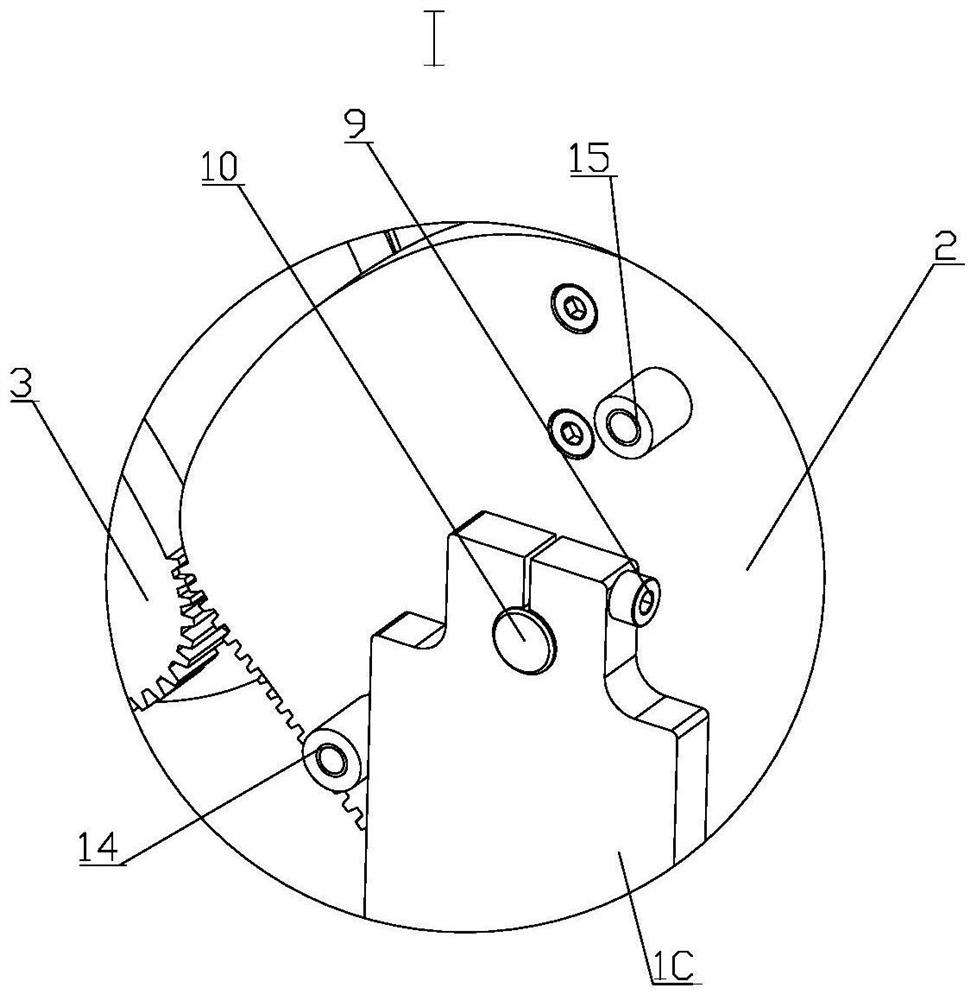
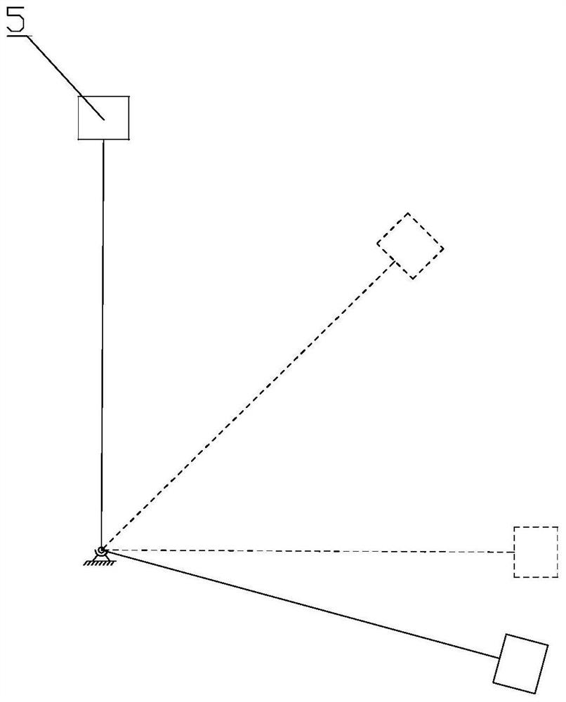
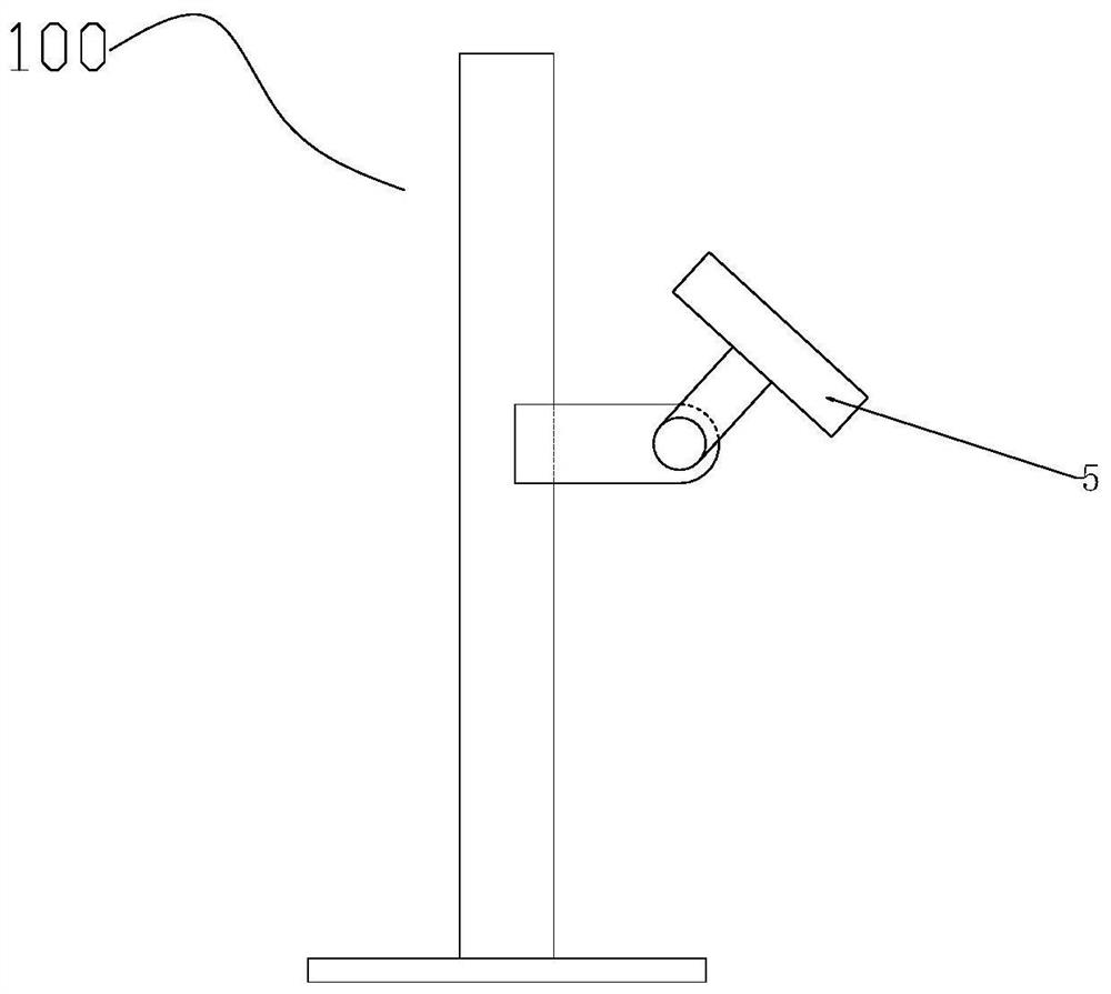
[0056] Such as Figure 3 ~ Figure 6 A moment balancer shown includes a base assembly 1, a driving gear 3 and a driven gear 2 which are arranged on the base assembly 1 and mesh with each other, an energy storage device 6 connected with the driving gear 3, and a driven gear 2 connected to the Connected load5.

[0057] Such as Figure 13 with Figure 14 As shown, the driving gear 3 revolves around its own main gear center O 1 Rotation, the driven gear 2 revolves around itself from the gear center O 2 Autorotation; between the driving gear 3 and the driven gear 2, a variable transmission ratio transmission is performed and a node P for position change is formed. The node P is known by common knowledge and w...


PUM


Abstract

The invention discloses a moment balancer. The moment balancer comprises a driven gear, a driving gear, a load and an energy storage device, wherein the driven gear and the driving gear are engaged with each other, the load is connected with the driven gear and rotates around the center of the driven gear, and the energy storage device is connected with the driving gear and provides torque for thedriving gear. Due to the fact that the driving gear and the driven gear are set to be in variable-transmission-ratio movement, the pitch line radiuses of the two gears at the instantaneous engaging position are continuously changed, so that the torque generated by the energy storage device on the driven gear through the driving gear and the torque generated by the load gravity adapt to each otherand counteract each other , the load can stably operate during rotation, and accordingly a device provided with the load, for example, an X-ray machine loaded with a flat panel detector operates stably.

Description

technical field [0001] The invention relates to the field of balancing devices, in particular to a moment balancer. Background technique [0002] In the current trajectory control process of some load devices, the external force and the instantaneous position of the load are constantly changing, and constantly changing torques are often generated. For example, a flat panel detector installed on a vertical X-ray machine requires the flat panel detector to rotate around a fixed point in a vertical plane. Assuming that the gravity of the flat panel detector is G, and the distance between the flat panel detector and the fixed point is L, then The moment Tg=G*L*sinα will be generated by the flat panel detector at any instantaneous position of α° with the vertical direction. In this way, the continuous change of the instantaneous torque of the flat panel detector will affect the stability of the entire system operation, and cause adverse effects on the normal operation of the X-r...

Claims


Application Information

Patent Timeline
Patent Type & Authority Applications(China)
IPC IPC(8): F16H33/10
CPCF16H33/10
Inventor 骆世先羿应财王政钧李仁攀吴胜勇
Owner 成都开图医疗系统科技有限公司
Why Eureka
Try Eureka