Monitoring equipment with protection mechanism

A technology for monitoring equipment and protective mechanisms, applied to mechanical equipment, cleaning methods using tools, supporting machines, etc., can solve problems such as small coverage, troublesome cleaning of dust, manual adjustment, etc., to increase the area that can be monitored and prevent collisions Damage and increase in service life

Pending Publication Date: 2021-01-08
田友云
View PDF10 Cites 9 Cited by
  • Summary
  • Abstract
  • Description
  • Claims
  • Application Information

AI Technical Summary

Problems solved by technology

[0003] The existing monitoring equipment is equipped with a protective cover to prevent the equipment from being exposed to the sun or rain for a long time, which has a certain protective effect. However, there are still some problems in the existing monitoring equipment. Most of the existing monitoring equipment needs to manually adjust the monitoring angle. , in the actual use process, the coverage area is small, and there are many monitoring blind spots. The existing monitoring equipment will accumulate more dust on the protective glass on the surface of the camera for a long time, and if it is not cleaned for a long time, the image acquisition will be blurred, but the monitoring The equipment is generally installed at a high place, which makes it more troublesome to clean up the dust, and the existing monitoring equipment has poor side protection and does not have a protective mechanism, which is easy to cause damage during transportation and other processes

Method used


Image

  • Monitoring equipment with protection mechanism
  • Monitoring equipment with protection mechanism
  • Monitoring equipment with protection mechanism

Examples


Embodiment Construction

[0023] The technical solutions in the embodiments of the present invention will be clearly and completely described below with reference to the accompanying drawings in the embodiments of the present invention. Obviously, the described embodiments are only a part of the embodiments of the present invention, but not all of the embodiments.

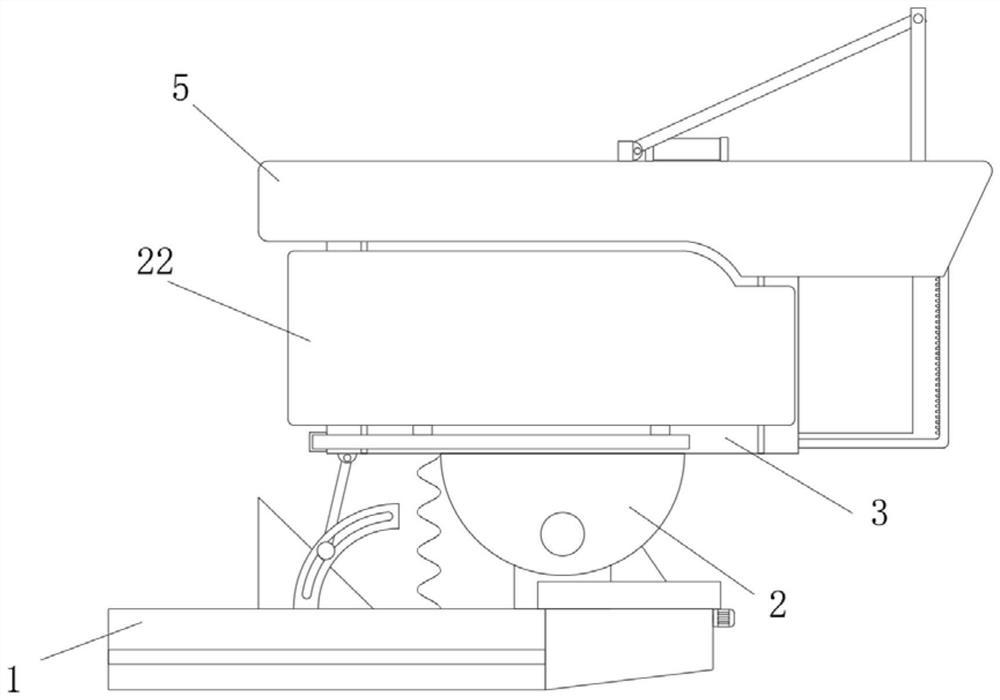
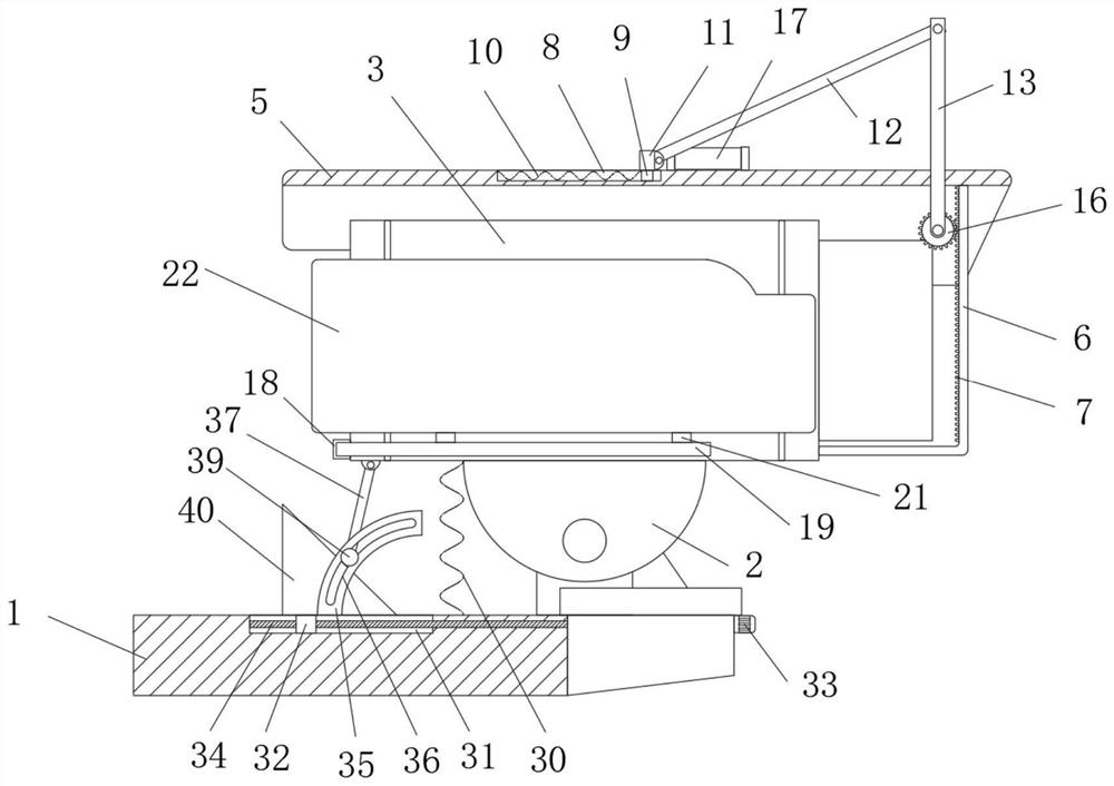
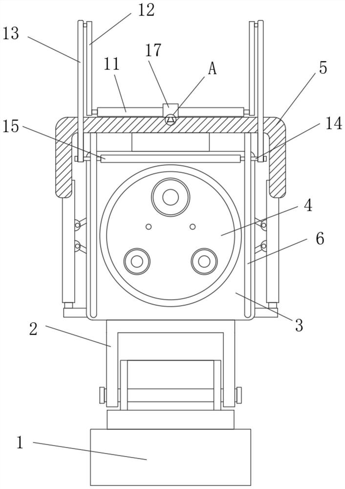
[0024] refer to Figure 1-7 , a monitoring device with a protective mechanism, comprising a mounting bracket 1, a movable mounting seat 2 is movably mounted on the right side of the upper surface of the mounting bracket 1, a camera body 3 is mounted on the upper surface of the movable mounting seat 2, and a fixed camera body 3 is mounted on the left side of the camera body 3 Column 24, two arc-shaped elastic plates 25 are installed on the outer side of the fixed column 24. The axial section of the arc-shaped elastic plate 25 is arc-shaped. When the protective plate 22 is squeezed or collided, the L-shaped movable rod 19 can be driven by the ...


PUM


Abstract

The invention relates to the technical field of monitoring equipment, in particular to monitoring equipment with a protective mechanism. The monitoring equipment with the protective mechanism comprises a mounting bracket, a movable mounting seat is movably mounted on the right side of the upper surface of the mounting bracket, and a camera body is mounted on the upper surface of the movable mounting seat. Protective glass is mounted on the right side of the camera body, a protective cover plate is installed on the upper surface of the camera body, an L-shaped fixing rod is installed on the right side of the lower surface of the protective cover plate, the end, away from the protective cover plate, of the L-shaped fixing rod is connected to the right side of the camera body, and a pluralityof teeth are sequentially arranged and installed on one side of the L-shaped fixing rod. The side face of the monitoring equipment can be protected through mutual cooperation of the structures, damage caused by impact or extrusion in the transportation or use process is prevented, the angle of the monitoring equipment can be conveniently adjusted, the protective glass can be conveniently cleaned,and the definition of an output image of the monitoring equipment is guaranteed.

Description

technical field [0001] The invention relates to the technical field of monitoring equipment, in particular to a monitoring equipment with a protective mechanism. Background technique [0002] A typical TV surveillance system is mainly composed of front-end equipment and back-end equipment. The front-end equipment is usually composed of cameras, manual or motorized lenses, pan / tilt, protective covers, monitors, alarm detectors and multi-function decoders. , they perform their respective duties, and establish corresponding connections with various equipment of the central control system through wired, wireless or optical fiber transmission media. In the actual TV monitoring system, these front-end equipment may not be used at the same time, but to achieve monitoring on-site images The collected cameras and lenses are essential, and the back-end equipment can be further divided into central control equipment and sub-control equipment. Nowadays, monitoring equipment is an import...

Claims


Application Information

Patent Timeline
Patent Type & Authority Applications(China)
IPC IPC(8): F16M11/10F16M11/18F16M11/02H04N5/225B08B1/00F16F15/06
CPCF16M11/10F16M11/18F16M11/02B08B1/006F16F15/06H04N23/51
Inventor 田友云
Owner 田友云
Why Eureka
Try Eureka