
Optical receiver and method for adjusting position of chip

An optical receiver and chip technology, applied in the field of optical communication, can solve the problems of difficult operation and difficult to meet the standard response current, and achieve the effects of optimizing the response current, reducing the difficulty of coupling, and reducing the cost

Pending Publication Date: 2021-01-08
武汉乾希科技有限公司 +1
View PDF6 Cites 1 Cited by
  • Summary
  • Abstract
  • Description
  • Claims
  • Application Information

AI Technical Summary

Problems solved by technology

[0003] However, in the existing solutions, the coupling method between the lens and the chip is many-to-many coupling, which often makes the actual operation of the coupling difficult, which in turn makes it difficult for the response current to reach the standard

Method used


Image

  • Optical receiver and method for adjusting position of chip
  • Optical receiver and method for adjusting position of chip
  • Optical receiver and method for adjusting position of chip

Examples


Embodiment Construction

[0023] Exemplary embodiments of the present application are described below in conjunction with the accompanying drawings, which include various details of the embodiments of the present application to facilitate understanding, and they should be regarded as exemplary only. Accordingly, those of ordinary skill in the art will recognize that various changes and modifications of the embodiments described herein can be made without departing from the scope and spirit of the application. Also, descriptions of well-known functions and constructions are omitted in the following description for clarity and conciseness.

[0024] In the description of the embodiments of the present disclosure, the term "comprising" and its similar expressions should be interpreted as an open inclusion, that is, "including but not limited to". The term "based on" should be understood as "based at least in part on". The term "one embodiment" or "the embodiment" should be read as "at least one embodiment...


PUM


Abstract

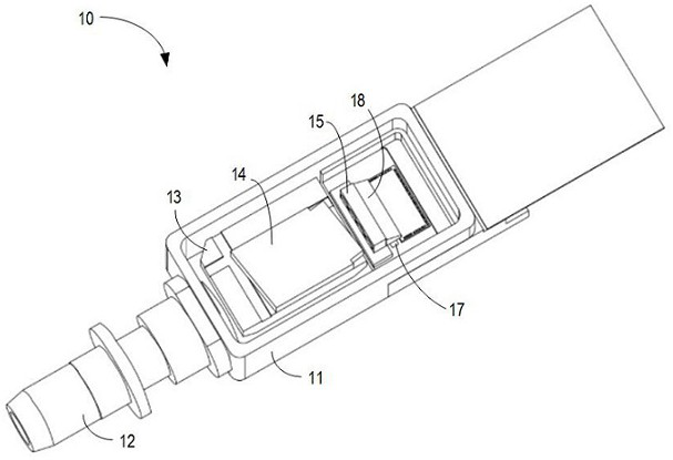
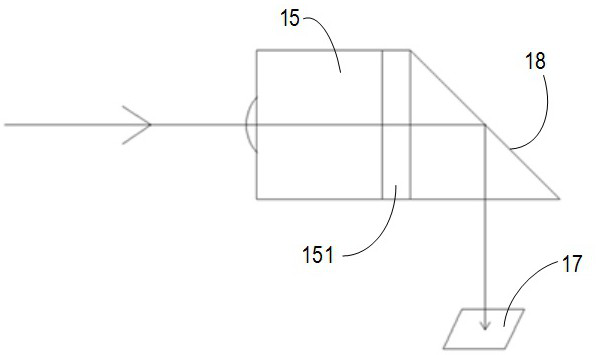
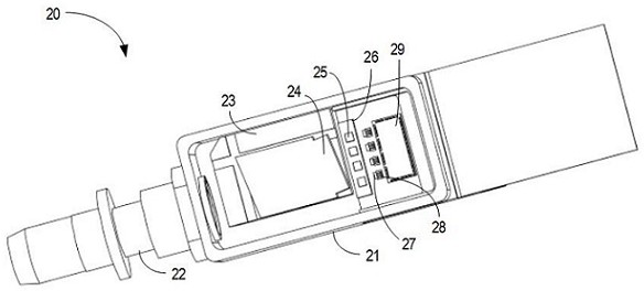
The invention relates to an optical receiver and a method for adjusting the position of a chip. The optical receiver comprises a shell body, an optical fiber adapter, an optical splitter, a pluralityof lenses, a plurality of chips anda plurality of chip carriers, wherein the optical fiber adapter is arranged outside the shell bodyand is coupled to the shell body; the optical splitter is arrangedon the inner side of the shell body; the plurality of lenses are disposed independently of each other and adjacent to the optical splitter; the plurality of chips are configured to convert light entering the shell body via the optical fiber adapter into an electrical signal, and each of the plurality of chips is disposed on a side, away from the optical splitter, of the respective lens; and the plurality of chip carriers are disposed perpendicular to a first direction of the light irradiation, each of the plurality of chips is coupled to the respective chip carrier, and a photosurface of the chip is perpendicular to the first direction of the light. According to the optical receiver and the method of the invention, the coupling efficiency of the optical receiver can be improved, and the cost of the optical receiver is reduced.

Description

technical field [0001] Embodiments of the present disclosure generally relate to the field of optical communications, and more particularly, to an optical receiver and a method of adjusting a position of a chip. Background technique [0002] With the promotion and popularization of 5G technology, people's requirements for increasing data transmission rates are more urgent. It is an effective method to use light as a medium for data transmission. In the field of optical communications, optical receivers are a common component. In the optical receiver, an optical signal carrying data is projected onto a lens and then projected onto a chip, thereby converting the optical signal to obtain the data information contained in the optical signal. [0003] However, in the existing solutions, the coupling mode between the lens and the chip is many-to-many coupling, which often makes the actual operation of the coupling more difficult, which in turn makes it difficult for the response...

Claims


Application Information

Patent Timeline
Patent Type & Authority Applications(China)
IPC IPC(8): G02B6/42G02B6/38
CPCG02B6/3825G02B6/4286G02B6/4287
Inventor 宋小飞廖传武贺亮王志文
Owner 武汉乾希科技有限公司
Learn More