Rotating device of mobile satellite antenna

A technology for moving satellites and rotating devices, applied in the direction of antenna support/installation device, antenna, antenna grounding switch structure connection, etc., can solve the problems of high cost, no signal, lost satellites, etc. Tear ability, prevent twisting, reduce friction loss effect

Active Publication Date: 2021-01-08
迪泰(浙江)通信技术有限公司
View PDF4 Cites 0 Cited by
  • Summary
  • Abstract
  • Description
  • Claims
  • Application Information

AI Technical Summary

Problems solved by technology

If the mobile carrier just turns around and changes direction by 180° quickly at this time, the limit device may be triggered, and the star will be lost. After that, the antenna will restart to search for the star, and there will be no signal state for a period of time, which will affect the customer experience.
[0004] In addition, the rotation of each axis of the mobile communication antenna also involves the problem of the transmission cable. At present, the cable threading methods mainly include conductive slip rings or cable straight-through. The production process of conductive slip rings requires high requirements and costs The cost is high and it cannot be popularized; if the cable is passed through directly, the risk of cable breakage is high

Method used


Image

  • Rotating device of mobile satellite antenna
  • Rotating device of mobile satellite antenna

Examples


Embodiment Construction

[0013] The present invention will be further described in detail below in conjunction with the accompanying drawings and embodiments.

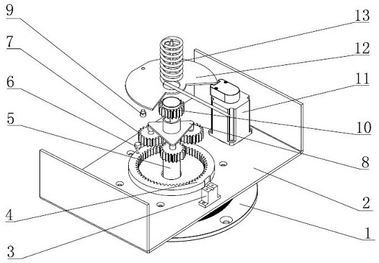
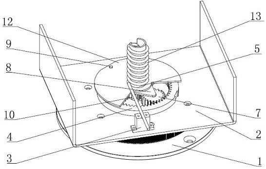
[0014] Such as figure 1 , 2 As shown, a rotating device for a mobile satellite antenna includes an antenna frame 2, a base 1, a motor 11, a driving pulley and a driven pulley, the base 1 is fixedly connected to a mobile carrier, and the antenna frame 2 is rotationally connected to the base 1. Belt pulley is coaxially fixedly connected with the drive shaft of motor 11, and the central axis of driven pulley and antenna frame 2 is coaxially arranged and both are fixed, and driving pulley and driven pulley are driven by belt, and the central position of base 1 is fixedly arranged with Winding column 5, winding column 5 passes through the central position of antenna frame 2, and antenna frame 2 is provided with planetary gear train angle limiting mechanism, and planetary gear train angle limiting mechanism includes ring gear 4, planet carrier 8, ...


PUM


Abstract

The invention discloses a rotating device of a mobile satellite antenna. The rotating device comprises an antenna rack, a base, a motor, a driving belt pulley and a driven belt pulley, the base is fixedly connected with a mobile carrier, the antenna rack is rotatably connected with the base, the driving belt pulley is coaxially and fixedly connected with a driving shaft of the motor, the driven belt pulley is coaxially arranged with the central axis of the antenna rack and fixed to the antenna rack, the device is characterized in that a planetary gear train angle limiting mechanism is arrangedon the antenna rack, a winding column is fixedly arranged in the center of the base, a spiral cable sleeves the winding column, a winding fixing seat is fixedly arranged on the antenna rack, one endof the spiral cable is fixed to the winding fixing seat, and the other end of the spiral cable is fixed to the top of the winding column. The rotating device has the advantages that the limiting device is prevented from being triggered possibly when the mobile carrier turns around quickly and reverses by 180 degrees, the phenomenon of satellite loss is avoided, and in addition, a coil of the spiral cable can shrink and diffuse freely in the rotating process of the antenna rack, so that the cable is prevented from being twisted off.

Description

technical field [0001] The invention relates to a mobile satellite antenna, in particular to a rotating device for a mobile satellite antenna. Background technique [0002] With the vigorous development of the satellite field in our country, the application of satellite terminal stations is no longer limited to being fixed on the ground, and gradually develops to the mobile carrier. On the mobile carrier, the mobile communication antenna must be used to ensure that the satellite antenna is always aligned with the satellite. Due to the displacement of the mobile carrier during driving, the satellite antenna needs to adjust the direction in time, and the direction adjustment needs to be limited within a certain range, otherwise the unlimited rotation will cause the cables inside the antenna to be entangled together, resulting in cable damage. Therefore, the mobile satellite needs to set a limit mechanism in the azimuth rotation device to limit its rotation range in the azimuth...

Claims


Application Information

Patent Timeline
Patent Type & Authority Applications(China)
IPC IPC(8): H01Q3/06H01Q1/12H01Q1/50
CPCH01Q3/06H01Q1/12H01Q1/50
Inventor 盛友旭蔡金平章文才贾建国
Owner 迪泰(浙江)通信技术有限公司
Why Eureka
Try Eureka