
Thermal switch and temperature control device with same

A thermal switch and heat source technology, applied in electric heating devices, electrical components, etc., can solve the problems of high processing accuracy, unfavorable equipment load reduction, difficult to open again, etc., to achieve high movement reliability, cost saving, reliable performance. Effect

Pending Publication Date: 2021-01-08
NINGBO INST OF MATERIALS TECH & ENG CHINESE ACADEMY OF SCI
View PDF0 Cites 2 Cited by
  • Summary
  • Abstract
  • Description
  • Claims
  • Application Information

AI Technical Summary

Problems solved by technology

For active-driven thermal switches, since an external controller is required to control the opening and closing of the thermal switch, it is easy to introduce additional heat, and involves circuits and additional structures, the cost is high, and it is not conducive to reducing the burden on the equipment; for passive contact type As for the thermal switch, its structure is more complicated, the processing precision is higher, and the response speed is slower, and cold welding is prone to occur when it is closed for a long time, and it is difficult to open it again

Method used


Image

  • Thermal switch and temperature control device with same
  • Thermal switch and temperature control device with same
  • Thermal switch and temperature control device with same

Examples


Embodiment Construction

[0024] The technical solutions in the embodiments of the present invention will be clearly and completely described below in conjunction with the accompanying drawings in the embodiments of the present invention. Obviously, the described embodiments are only part of the embodiments of the present invention, not all of them. Based on the implementation manners in the present invention, all other implementation manners obtained by persons of ordinary skill in the art without making creative efforts belong to the scope of protection of the present invention.

[0025] It should be noted that when a component is said to be "connected to" another component, it may be directly connected to the other component or there may be an intervening component. When a component is said to be "set on" another component, it may be set directly on the other component or there may be an intervening component at the same time. When a component is said to be "fixed" to another component, it may be di...


PUM


Abstract

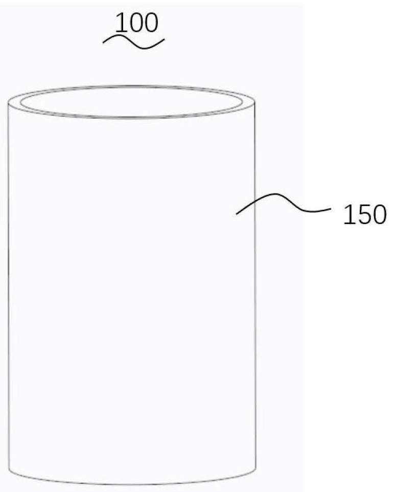
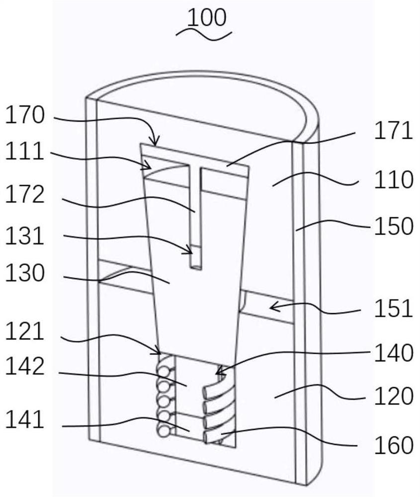
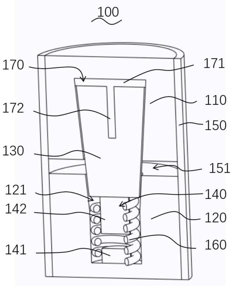
The invention relates to a thermal switch and a temperature control device with the same. The thermal switch comprises a first heat conduction part, a second heat conduction part, a sliding part and an attraction assembly, wherein the second heat conduction part and the first heat conduction part are oppositely arranged, and the sliding part is arranged between the first heat conduction part and the second heat conduction part; the attraction assembly comprises a permanent magnet and a magnetic element, wherein one of the permanent magnet and the magnetic element is fixedly connected to the sliding part, and the other one is directly or indirectly fixed to the second heat conduction part and arranged opposite to the permanent magnet; the magnetism of the magnetic element can respond to thetemperature change of the second heat conduction part, and the permanent magnet can drive the sliding part to slide between the first heat conduction part and the second heat conduction part throughthe magnetic force change between the permanent magnet and the magnetic element and be switched between the closing position and the opening position, so that the thermal path connection between the first heat conduction part and the second heat conduction part is closed or disconnected.

Description

technical field [0001] The invention relates to the technical field of temperature control, in particular to a thermal switch and a temperature control device having the same. Background technique [0002] Many applications in the field of thermal control require two components to be able to achieve autonomous thermal connection and autonomous thermal separation under different working conditions. [0003] This switching is currently possible with thermal switches. For active-driven thermal switches, since an external controller is required to control the opening and closing of the thermal switch, it is easy to introduce additional heat, and involves circuits and additional structures, the cost is high, and it is not conducive to reducing the burden on the equipment; for passive contact type As for the thermal switch, its structure is more complicated, the processing precision is higher, and the response speed is slower, and it is prone to cold welding when it is closed for...

Claims


Application Information

Patent Timeline
Patent Type & Authority Applications(China)
IPC IPC(8): H05B1/02
CPCH05B1/0202H05B1/0219
Inventor 李晋阳刘剑
Owner NINGBO INST OF MATERIALS TECH & ENG CHINESE ACADEMY OF SCI
Learn More