Component for a machine tool, machine tool and method for identifying wear

A component and machine tool technology that is applied to presses, mechanical equipment, and testing wear resistance, etc., can solve problems such as deterioration of conditions and achieve high processing quality

Pending Publication Date: 2021-01-08
BYSTRONIC LASER
View PDF13 Cites 0 Cited by
  • Summary
  • Abstract
  • Description
  • Claims
  • Application Information

AI Technical Summary

Problems solved by technology

Delivery times for replacement parts often exacerbate the situation

Method used


Image

  • Component for a machine tool, machine tool and method for identifying wear
  • Component for a machine tool, machine tool and method for identifying wear
  • Component for a machine tool, machine tool and method for identifying wear

Examples


Embodiment Construction

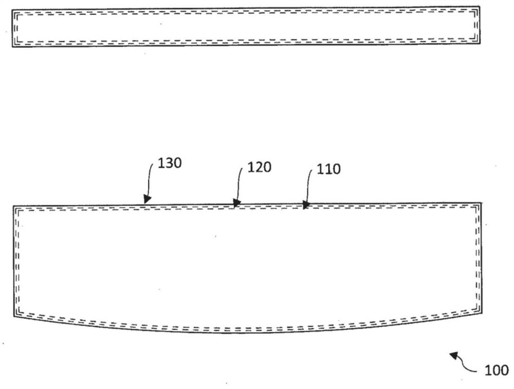
[0040] figure 1 A schematic front view and a plan view of a component 100 are shown, which have a component core or component base body 110 and optical wear indicators 120 , 130 applied thereto. The component 100 can be a wear part of a bending machine, in particular a tool, a machine table and / or a stop element such as a stop finger. Correspondingly, the wearing part of the bending machine can comprise the base body 110 and the optical wear indicators 120 , 130 arranged thereon.

[0041] Depending on the intended use, the component 100 is provided with an outer hard material layer or a sacrificial layer 130 . Examples of materials here include PVD and / or CVD hard material layers or materials such as titanium nitride. The layer thickness is selected according to the application and the expected component wear. The layer thickness is advantageously from 1 to 10 micrometers and especially advantageously from 1 to 20 micrometers. In addition, larger layer thicknesses can also...


PUM


Abstract

The invention relates to a component (100, 400) for a machine tool, comprising a component main body (110) and at least two layers (120, 130; 440, 450), arranged on said main body, for identifying wear, the layers (120, 130; 440, 450) for identifying wear being applied to a wear region of a component (100, 400) of the machine tool and at least one of the two layers (120, 130; 440, 450) being a signalling layer (120) for indicating the wear.

Description

technical field [0001] The invention relates to a component for a machine tool, a machine tool and a method for detecting wear. In particular, the invention relates to a component for a machine tool according to claim 1 , a machine tool according to claim 10 and a method for detecting wear according to claim 14 . Background technique [0002] Machine tools are used to manufacture and process workpieces using tools. For example, sheet metal processing machines, in particular bending machines or pressing machines such as press brakes, are considered machine tools here. In the following text reference is made to a press brake for the sake of clarity. [0003] Precisely set machine axes and a dimensionally stable machine geometry are required for the production of high-quality and precisely bent parts on press brakes. Continuous operation inevitably leads to wear of the machine and wear and tear of the bending machine, in particular of the stressed components. In normal oper...

Claims


Application Information

Patent Timeline
Patent Type & Authority Applications(China)
IPC IPC(8): B30B15/06F16D66/02G01N3/56
CPCB30B15/06B21D5/02B21D55/00
Inventor 拉尔斯·沃伊达斯基
Owner BYSTRONIC LASER
Why Eureka
Try Eureka