Adjustable multifunctional agricultural sprinkling irrigation equipment
A multi-functional and adjustable technology, applied in agriculture, botany equipment and methods, animal husbandry, etc., can solve the problems of inability to adjust the irrigation angle, reduce work stability, and reduce irrigation performance, so as to increase irrigation effect and support Excellent, easy-to-use effect
- Summary
- Abstract
- Description
- Claims
- Application Information
AI Technical Summary
Problems solved by technology
Method used
Image
Examples
Embodiment 1
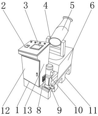
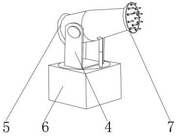
[0030] Embodiment one, such as Figure 4 , 5 As shown, the positioning frame 401 is located at the upper end of the rotating seat 405, the positioning member 406 and the bearing ring 407 are located at the outer wall of the rotating seat 405, the positioning member 406 is located at the two ends of the bearing ring 407, and the positioning pin 402 is located at the inner side of the upper end of the positioning frame 401. The support 404 is positioned at the upper end of the rotating base 405, the movable connecting plate 403 is positioned at the upper end of the elevating bracket 404, a fixed seat is arranged between the positioning frame 401 and the rotating seat 405, and the lower end of the positioning frame 401 is fixedly connected with the upper end of the rotating base 405 through the fixed seat A mounting seat is arranged between the lifting bracket 404 and the rotating base 405, the upper end of the rotating base 405 is fixedly connected with the lower end of the lift...
Embodiment 2
[0031] Embodiment two, such as Image 6 As shown, the disassembly head 701 is located on one side of the thread 702, the thread 702 is located on the outer wall of the disassembly head 701, the clip 706 is located inside the nozzle 703, the adjustment seat 704 is located on the outer surface of the clip 706, and the sprinkling port 705 is located on the adjustment seat One end of 704, a welding block is arranged between the dismounting head 701 and the nozzle 703, and one end of the dismounting head 701 is fixedly connected with one end of the nozzle 703 through the welding block, and a clip is arranged between the nozzle 703 and the clamping plate 706, and the nozzle 703 The inner side of the clamp is fixedly connected with the outer wall of the clamping plate 706, and the outer surface of the clamping plate 706 is movably connected with one end of the sprinkler port 705 through the adjustment seat 704, which can increase the use function of the equipment. The sprinkler head is ...
Embodiment 3
[0032] Embodiment three, such as Figure 7 As shown, the installation slot 1102 is located at the upper end of the positioning base 1101, the positioning slot 1104 is located at the lower end of the positioning base 1101, the anti-skid pad 1103 is located at the outer surface of the positioning slot 1104, the installation partition 1105 is located inside the installation slot 1102, and the positioning base 1101 A connecting groove is provided between the positioning slot 1104, the lower end of the positioning base 1101 is fixedly connected with the upper end of the positioning slot 1104 through the connecting slot, superglue is arranged between the anti-skid pad 1103 and the positioning slot 1104, and the positioning slot 1104 The outer surface is fixedly connected with the inner surface of the anti-skid pad 1103 by superglue, which increases the stability of the equipment and is easy to use.
PUM
 Abstract
Description
Claims
Application Information
 - R&D
- Intellectual Property
- Life Sciences
- Materials
- Tech Scout
- Unparalleled Data Quality
- Higher Quality Content
- 60% Fewer Hallucinations
Browse by: Latest US Patents, China's latest patents, Technical Efficacy Thesaurus, Application Domain, Technology Topic, Popular Technical Reports.
© 2025 PatSnap. All rights reserved.Legal|Privacy policy|Modern Slavery Act Transparency Statement|Sitemap|About US| Contact US: help@patsnap.com


