Injection mold facilitating discharging
A technology of injection molds and moulds, which is applied in the field of injection molds that are easy to discharge, can solve the problems that products are easy to stick to the injection mold and are difficult to take out, and achieve the effects of increasing the discharging speed, improving the cooling effect, and improving the processing quality
- Summary
- Abstract
- Description
- Claims
- Application Information
AI Technical Summary
Problems solved by technology
Method used
Image

Examples
specific Embodiment approach 1
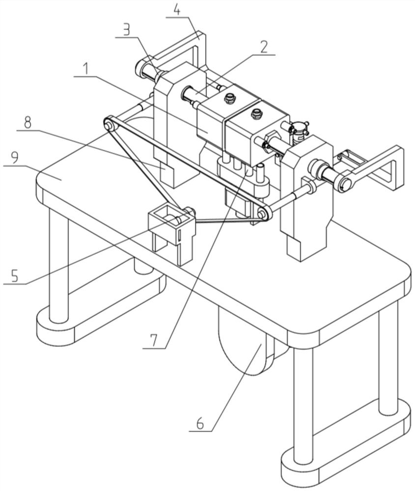
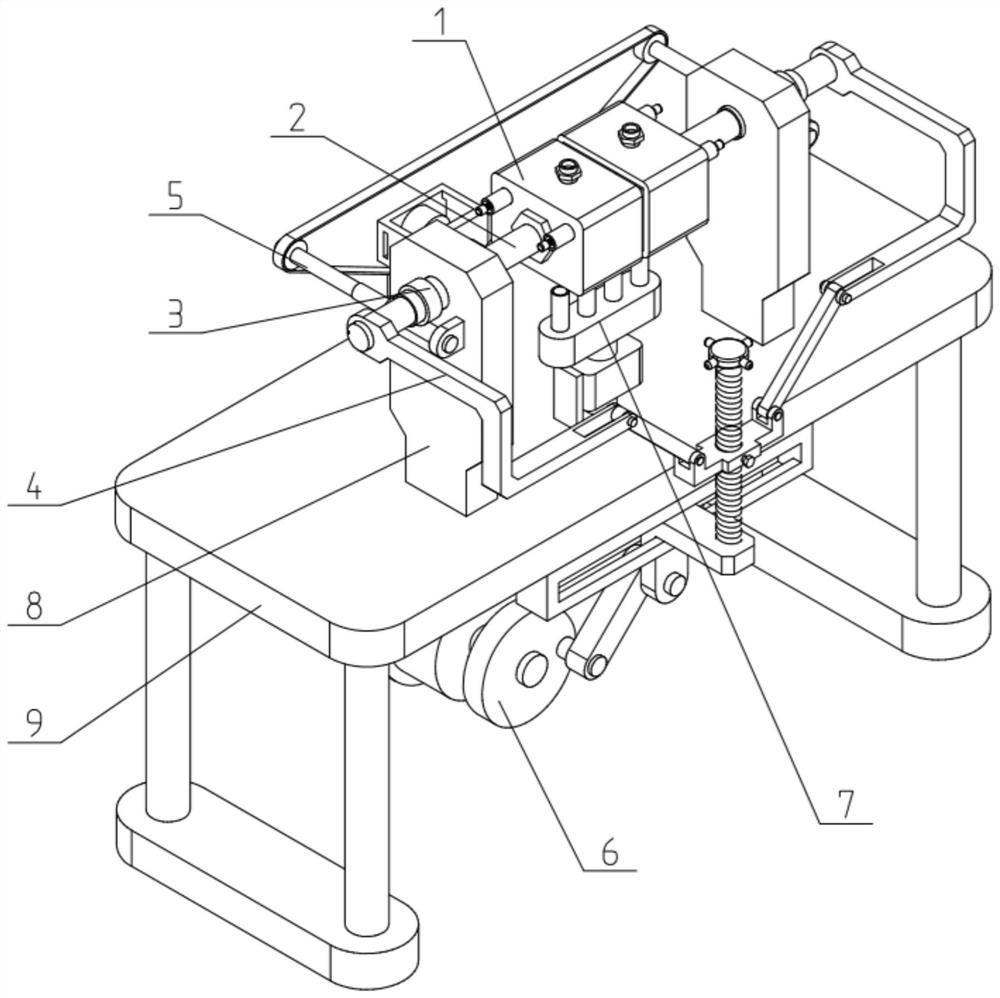
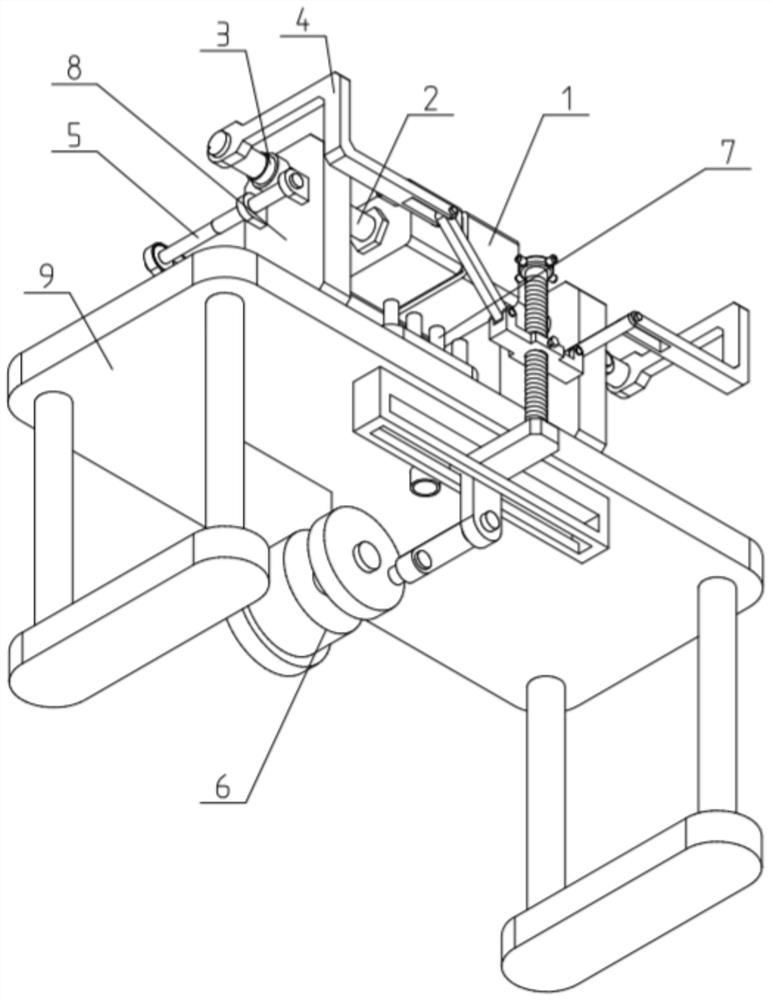
[0039] like Figure 1-12 As shown, an injection mold that is convenient for discharging includes a movable mold mechanism 1, a push rod mechanism 2, a rotating tube mechanism 3, a mold clamping control mechanism 4, a rotation control mechanism 5, a shaking and demoulding mechanism 6, an air cooling mechanism 7, Vertical frame 8 and frame 9; Described movable mold mechanism 1 is provided with two, and two described movable mold mechanisms 1 are relatively fixed on the inner end of two described push rod mechanisms 2, two described push rod mechanisms 2 The middle part of the sliding fit in the two rotating tube mechanisms 3; the outer ends of the two push rod mechanisms 2 are connected to the two ends of the clamping control mechanism 4; the middle of the clamping control mechanism 4 is fitted Connected in the middle of the frame 9; the oscillating demoulding mechanism 6 is fixedly connected to the frame 9, and the oscillating demoulding mechanism 6 is transmission-connected to...
specific Embodiment approach 2
[0041] like Figure 1-12 As shown, the movable mold mechanism 1 includes a movable mold body 101 with an open inner end and an injection pipe 102 with a check valve; the injection pipe 102 is fixed on the movable mold body 101; two of the movable molds The movable mold bodies 101 of the mechanism 1 are arranged oppositely, and the movable mold bodies 101 of the two movable mold mechanisms 1 are sealed and fastened together to form the injection mold body. The movable mold bodies 101 inside the two movable mold mechanisms 1 are sealed and fastened together to form the injection mold body, and the injection molding slurry can be injected into the injection molding processing area inside the injection mold body through any one of the injection pipes 102 with a one-way valve. So as to carry out injection molding work.
specific Embodiment approach 3
[0043] like Figure 1-12 As shown, the movable mold mechanism 1 also includes an ejector assembly 103; the outer end of the movable mold body 101 is provided with an ejector assembly 103; the ejector assembly 103 includes a fixed pipe 103A, an ejector block 103B, a limit Plate 103C, sliding rod 103D, compression spring 103E and spring seat 103F; the fixed tube 103A is sealed and fixed in the circular through hole at the outer end of the movable mold body 101, and the inner tube surface of the fixed tube 103A is in contact with the movable mold body The inner surfaces of 101 are coplanar; the ejection block 103B and the spring seat 103F are respectively fixed on the inner and outer ends of the sliding rod 103D, and the ejection block 103B is sealed and slidably fitted in the fixed pipe 103A, and the ejection block 103B is blocked on the inner side of the limiting plate 103C; the inner side of the ejection block 103B is coplanar with the inner side of the fixed tube 103A, and th...
PUM
 Abstract
Description
Claims
Application Information
 - R&D
- Intellectual Property
- Life Sciences
- Materials
- Tech Scout
- Unparalleled Data Quality
- Higher Quality Content
- 60% Fewer Hallucinations
Browse by: Latest US Patents, China's latest patents, Technical Efficacy Thesaurus, Application Domain, Technology Topic, Popular Technical Reports.
© 2025 PatSnap. All rights reserved.Legal|Privacy policy|Modern Slavery Act Transparency Statement|Sitemap|About US| Contact US: help@patsnap.com