Lifting material carrying device

A handling device and material technology, applied in the field of warehouse material storage, can solve the problems of inflexibility, troublesome operation and high cost, and achieve the effect of avoiding direct contact friction, avoiding inconvenient movement, and reducing manpower handling.

Inactive Publication Date: 2021-01-12
马鞍山维拓商贸有限公司
View PDF0 Cites 0 Cited by
  • Summary
  • Abstract
  • Description
  • Claims
  • Application Information

AI Technical Summary

Problems solved by technology

[0002] When moving goods over short distances, such as moving goods from one place to another, or from a train to a warehouse, or from a warehouse to a truck, a forklift is often required. Traditional forklifts In the process of transporting goods, once a stepped climbing path is encountered, the forklift cannot climb up with the goods, but needs to use a crane to lift the forklift or the goods to the desired position, which is very troublesome and inefficient. , high cost, inflexible mobility
Moreover, some forklifts on the market are complex in structure, relatively high in cost, relatively heavy in weight, and difficult to operate. Therefore, we have improved this and proposed a lifting material handling device

Method used


Image

  • Lifting material carrying device
  • Lifting material carrying device
  • Lifting material carrying device

Examples


Embodiment

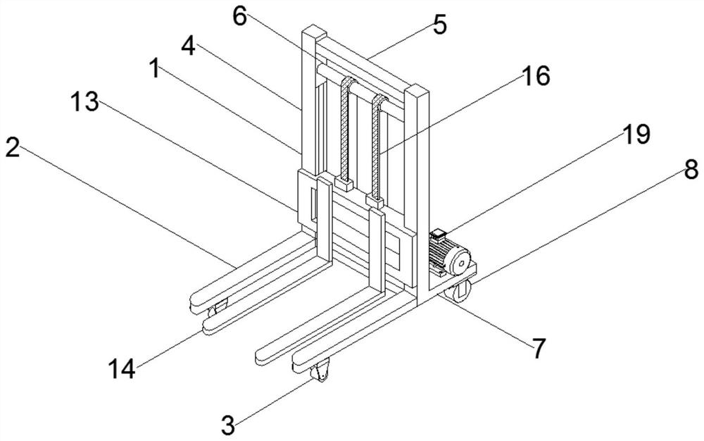
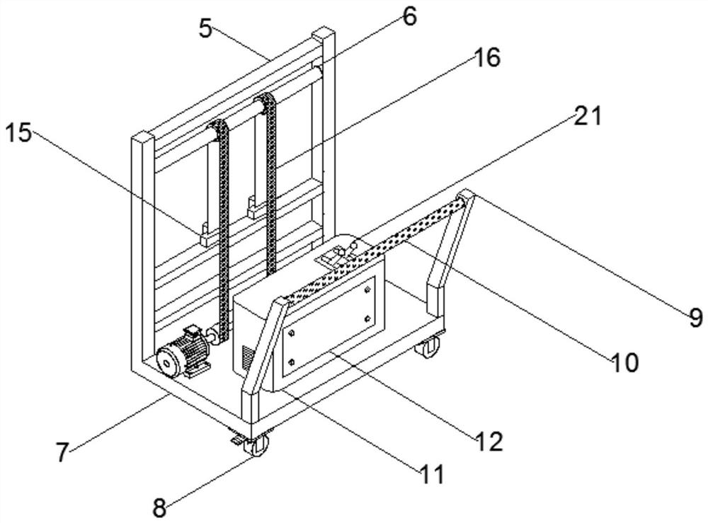
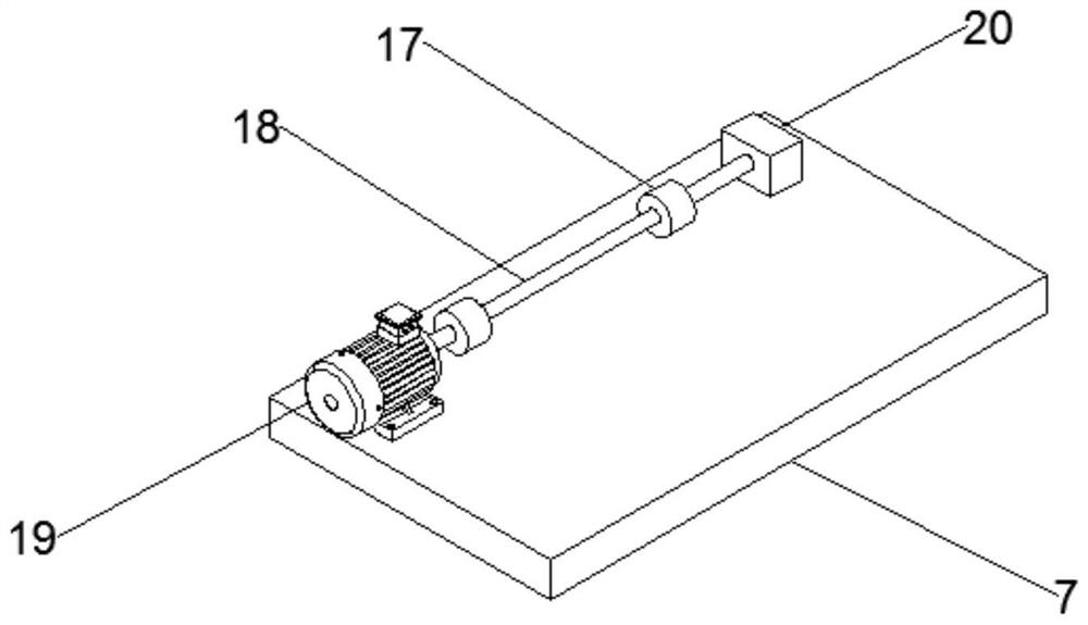
[0018] Example: such as Figure 1-3 As shown, a lifting material handling device of the present invention includes a car body 1, a carrier frame 2 is provided at the bottom of the car body 1, a pulley 3 is fixedly connected to one end of the bottom of the carrier frame 2, and a column 4 is vertically fixedly connected to the other end of the top of the carrier frame 2 , the top of the column 4 is fixedly connected with a beam 5, the bottom of the beam 5 is provided with a rotating shaft 6, the two ends of the rotating shaft 6 are rotationally connected with one side of the top of the column 4, the other side of the column 4 is fixedly connected with a bottom plate 7, and the bottom of the bottom of the bottom plate 7 is connected by two corner bolts There are universal wheels 8, and the top of the universal wheels 8 is provided with a foot brake, and the two corners of the outer top of the bottom plate 7 are fixedly connected with handrail columns 9, which are hollow polyhedral...


PUM


Abstract

The invention discloses a lifting material carrying device which comprises a vehicle body. A bearing frame is arranged at the bottom of the vehicle body; pulleys are fixedly connected to one end of the bottom of the bearing frame; upright columns are vertically and fixedly connected to the other end of the top of the bearing frame; a beam is fixedly connected to the tops of the upright columns; arotating shaft is arranged at the bottom of the beam; the two ends of the rotating shaft are rotationally connected with one sides of the tops of the upright columns respectively; a bottom plate is fixedly connected to the other sides of the upright columns; universal wheels are connected to the two corners of the bottom of the outer side of the bottom plate through bolts respectively; foot brakesare arranged on the tops of the universal wheels respectively; handrail upright columns are fixedly connected to the two corners of the top of the outer side of the bottom plate respectively; each handrail upright column is of a hollow polyhedron structure; a cross rod is fixedly connected to one sides of the tops of the handrail upright columns and is of a hollow cylinder structure; an antiskidrubber sleeve is connected to the periphery of the cross rod in a sleeved manner; a control box is fixedly connected to the top of the bottom plate; and an overhaul baffle plate is connected to the outer side of the control box through bolts. For the lifting material carrying device, by adding a lifting carrying structure of materials, the self-weight of the device is reduced, and the lifting material carrying device is very convenient and practical.

Description

technical field [0001] The invention relates to the technical field of warehouse material storage, in particular to a lifting material handling device. Background technique [0002] When moving goods over short distances, such as moving goods from one place to another, or from a train to a warehouse, or from a warehouse to a truck, a forklift is often required. Traditional forklifts In the process of transporting goods, once a stepped climbing path is encountered, the forklift cannot climb up with the goods, but needs to use a crane to lift the forklift or the goods to the desired position, which is very troublesome and inefficient. , the cost is high, and the mobility is inflexible. Moreover, some forklifts on the market are complex in structure, relatively high in cost, relatively heavy in weight, and difficult to operate. Therefore, we improve this and propose a lifting material handling device. Contents of the invention [0003] In order to solve the problems of the ...

Claims


Application Information

Patent Timeline
Patent Type & Authority Applications(China)
IPC IPC(8): B66F9/075B66F9/08B66F9/12B66F9/24F16G1/00
CPCB66F9/075B66F9/08B66F9/12B66F9/24F16G1/00
Inventor 李波宋大名
Owner 马鞍山维拓商贸有限公司
Why Eureka
Try Eureka