Gas turbine engine generator
A gas turbine and engine technology, applied in the direction of gas turbine devices, engine components, engine functions, etc., to achieve the effect of direct assembly and disassembly
- Summary
- Abstract
- Description
- Claims
- Application Information
AI Technical Summary
Problems solved by technology
Method used
Image

Examples
Embodiment Construction
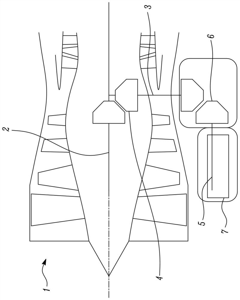
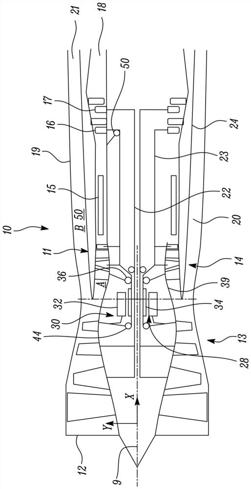
[0051] figure 2 and image 3 A gas turbine engine in the form of a low-bypass turbofan 10 with a main axis of rotation 9 is shown. The axis of rotation 9 defines a rearward direction X substantially parallel to the air flow through the engine 10 , a forward direction opposite to this rearward direction, and a radial direction Y. The engine 10 includes an air intake 12 and a pusher fan / low pressure compressor 13 that generates two airflows: a core airflow A and a bypass airflow B. The gas turbine engine 10 includes a core 11 receiving a core flow A. As shown in FIG. The engine core 11 includes a high-pressure compressor 14 , a combustion device 15 , a high-pressure turbine 16 , a low-pressure turbine 17 and a core exhaust nozzle 18 in series in axial flow. A nacelle 19 surrounds the gas turbine engine 10 and defines a bypass conduit 20 and a bypass exhaust nozzle 21 . The bypass airflow B flows through a bypass duct 50 delimited by a radially inner wall in the form of the ...
PUM
 Abstract
Description
Claims
Application Information
 - R&D Engineer
- R&D Manager
- IP Professional
- Industry Leading Data Capabilities
- Powerful AI technology
- Patent DNA Extraction
Browse by: Latest US Patents, China's latest patents, Technical Efficacy Thesaurus, Application Domain, Technology Topic.
© 2024 PatSnap. All rights reserved.Legal|Privacy policy|Modern Slavery Act Transparency Statement|Sitemap