
Reciprocating pump plunger sealing structure

A sealing structure and technology for reciprocating pumps, applied in the field of reciprocating pumps, can solve the problems of reduced effective sealing effect, insufficient pressing force of intermediate packing rings, shortened life of packing rings, etc., and achieve the effect of reducing wear and tear

Active Publication Date: 2021-01-12
重庆水泵厂有限责任公司
View PDF6 Cites 1 Cited by
  • Summary
  • Abstract
  • Description
  • Claims
  • Application Information

AI Technical Summary

Problems solved by technology

[0003] Existing conventional technology can refer to appendix figure 2 , a plunger sealing structure for a reciprocating pump, including a plunger 1 and a stuffing box 2 sleeved outside the plunger, a cavity is provided between the plunger and the stuffing box, and a cavity is set in the cavity The stuffing box gland 3 and the packing unit on the top, the stuffing box gland 3 is fixedly connected with the end of the stuffing box close to the outside, and the stuffing unit includes a packing assembly 4 composed of several packing rings and a spring against one end of the packing assembly 5. The other end of the packing assembly abuts against the inner end surface of the stuffing box gland, and the other end of the spring abuts against the inner end surface of the stuffing box close to the high pressure side, and the packing assembly is pushed together by the force of the spring and the stuffing box gland. Axially compressed, so that the packing ring in the packing assembly is radially deformed and the plunger is clamped, but there will be an obvious disadvantage in this design, that is, generally to enhance the sealing performance, the packing assembly is generally composed of multiple packing rings, the number If there are too many, the compression force of the middle packing ring is insufficient, and the effective sealing effect is reduced. In order to achieve the sealing effect, only increase the pre-tightening force at both ends, but this will lead to faster wear of the packing rings at both ends and shorten the life of the packing ring

Method used


Image

  • Reciprocating pump plunger sealing structure
  • Reciprocating pump plunger sealing structure

Examples


Embodiment Construction

[0015] The present invention will be further described in detail below in conjunction with the accompanying drawings.

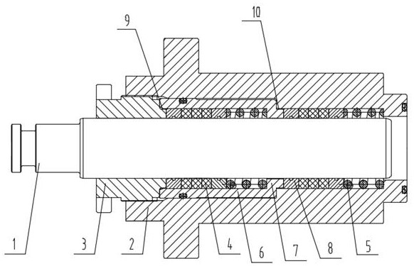
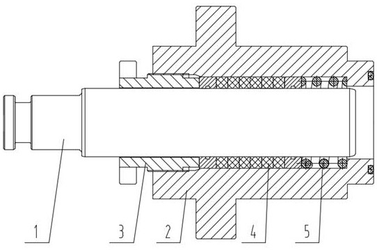
[0016] For specific implementation: see figure 1 , a plunger sealing structure for a reciprocating pump, including a plunger 1 and a stuffing box 2 sleeved outside the plunger, a cavity is provided between the plunger and the stuffing box, and a cavity is set in the cavity The stuffing box gland 3 and the packing unit on the top, the stuffing box gland is fixedly connected with the end of the stuffing box close to the outside, the stuffing unit includes a packing assembly 4 composed of several packing rings and a spring 5 abutting against one end of the packing assembly , there are at least two packing units along the axial direction of the plunger, one end of the packing unit closest to the external side is in contact with the inner end surface of the gland 3 of the stuffing box, and one end of the packing unit closest to the high pressure side of the plung...


PUM


Abstract

The invention discloses a reciprocating pump plunger sealing structure. The reciprocating pump plunger sealing structure comprises a plunger and a packing box arranged outside the plunger in a sleeving mode; a cavity is formed between the plunger and the packing box, a packing box gland arranged on the plunger in a sleeving mode and packing units are arranged in the cavity, and the packing box gland is fixedly connected with the end, close to the outside, of the packing box; each packing unit comprises a packing assembly composed of a plurality of packing rings and springs abutting against oneend of the packing assembly; the number of the packing units in the axial direction of the plunger is at least two, supporting sleeve pipes arranged on the packing units in a sleeving mode are further arranged in the cavity, one end of each supporting sleeve pipe extends in the direction of the central axis to form an annular protruding part; and every two adjacent packing units are correspondingly propped against the two axial ends of the annular protruding part on one supporting sleeve pipe. According to the reciprocating pump plunger sealing structure, abrasion of the packing rings is notincreased while the sealing effect is guaranteed, and the service life of the packing assembly is prolonged.

Description

technical field [0001] The invention belongs to the technical field of reciprocating pumps, in particular to a plunger sealing structure of a reciprocating pump. Background technique [0002] In the reciprocating pump, the plunger reciprocates. In order to seal the high-pressure liquid in the inner cavity of the reciprocating pump, a packing assembly is provided on the surface of the plunger. The packing assembly is generally composed of a plurality of packing rings. To deform in the direction, clamp the plunger, eliminate the gap between the packing component and the plunger surface, and achieve the sealing effect. [0003] Existing conventional technology can refer to appendix figure 2 , a plunger sealing structure for a reciprocating pump, including a plunger 1 and a stuffing box 2 sleeved outside the plunger, a cavity is provided between the plunger and the stuffing box, and a cavity is set in the cavity The stuffing box gland 3 and the packing unit on the top, the stu...

Claims


Application Information

Patent Timeline
IPC IPC(8): F04B53/02
CPCF04B53/02
Inventor 陈礼郭伟谭平王军符义红王文文
Owner 重庆水泵厂有限责任公司
Features
  • Generate Ideas
  • Intellectual Property
  • Life Sciences
  • Materials
  • Tech Scout
  • Unparalleled Data Quality
  • Higher Quality Content
  • 60% Fewer Hallucinations
Learn More