Bearing pedestal transformation structure and method for rolling bearing operation state in-situ monitoring
A running state, rolling bearing technology, applied in mechanical bearing testing, bearing components, shafts and bearings, etc., can solve the problems of inability to realize rolling bearing rolling behavior, in-situ monitoring of load distribution running state, etc., and achieve the effect of avoiding stress concentration
- Summary
- Abstract
- Description
- Claims
- Application Information
AI Technical Summary
Problems solved by technology
Method used
Image
Examples
Embodiment Construction
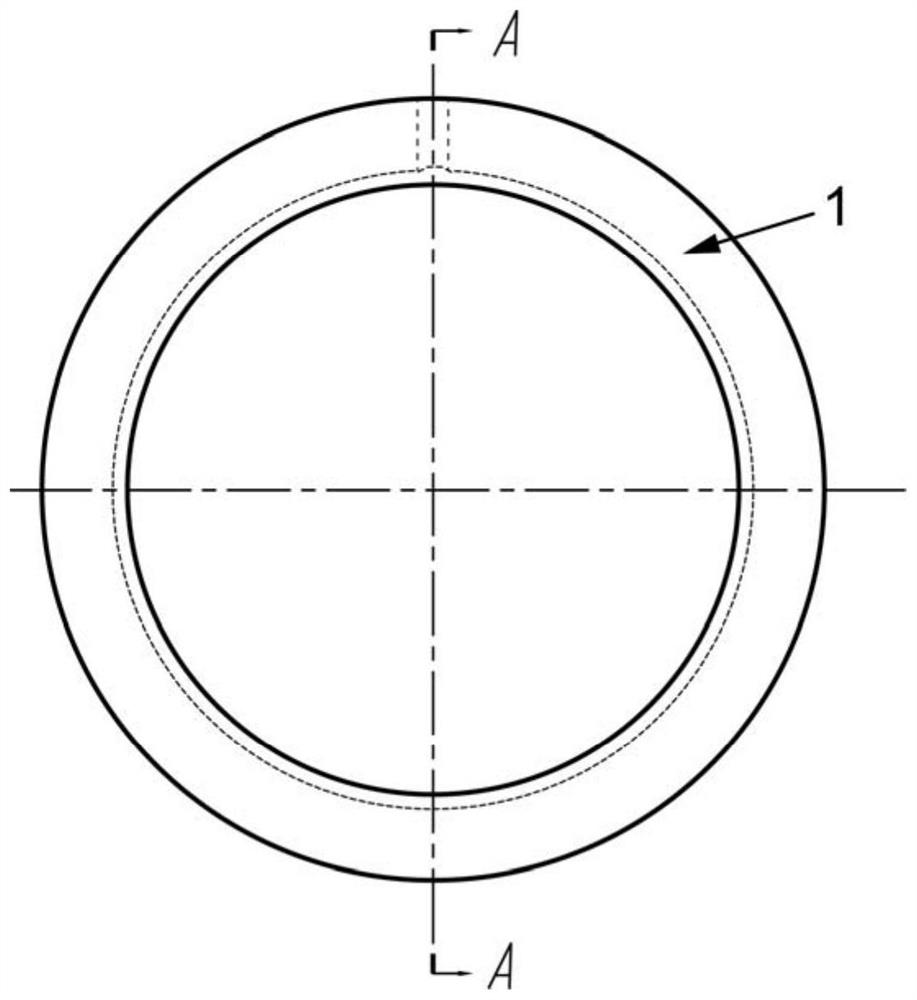
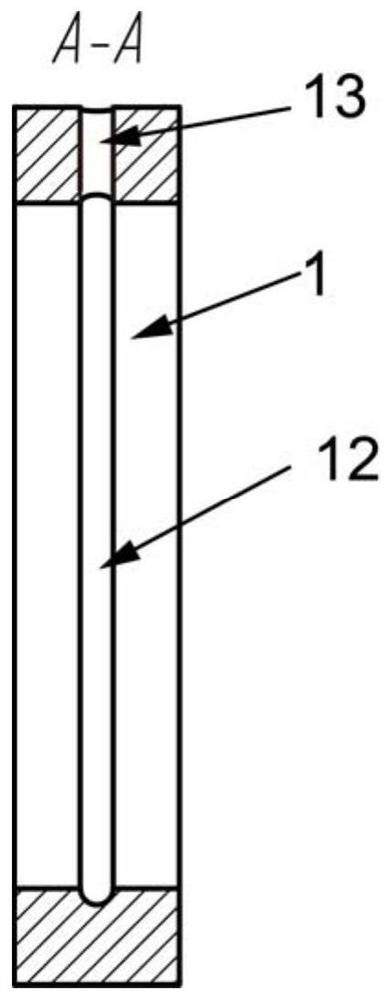
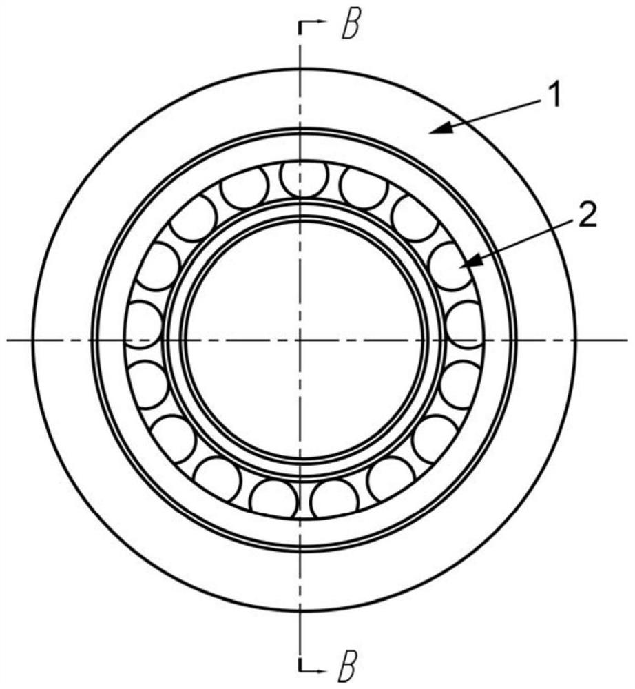
[0027] like figure 1 , figure 2 As shown, the present invention provides a bearing seat reconstruction structure and method for on-site monitoring of rolling bearing operation status, wherein the bearing seat 1 can represent the bearing seat of a rolling bearing in any mechanical system, and the bearing seat 1 and the test bearing 2 are matched. An annular groove 12 is processed in the circumferential direction on the inner surface, thereby providing enough arrangement space for the strain sensor 3 (such as Figure 5 As shown, the strain sensor 3 is pasted on the annular outer wall of the outer ring 21 of the test bearing 2). Moreover, the modification brought by the annular channel 12 to the various azimuth angles of the bearing seat is exactly the same, thereby ensuring that the modification to the bearing seat will not change the operating state such as the internal load distribution of the test bearing 2 . The cross-sectional shape of the annular channel 12 is arc-shape...
PUM
 Abstract
Description
Claims
Application Information
 - R&D
- Intellectual Property
- Life Sciences
- Materials
- Tech Scout
- Unparalleled Data Quality
- Higher Quality Content
- 60% Fewer Hallucinations
Browse by: Latest US Patents, China's latest patents, Technical Efficacy Thesaurus, Application Domain, Technology Topic, Popular Technical Reports.
© 2025 PatSnap. All rights reserved.Legal|Privacy policy|Modern Slavery Act Transparency Statement|Sitemap|About US| Contact US: help@patsnap.com


