Device for simulating rolling bearing slipping
A technology for rolling bearings and power devices, applied in the direction of mechanical bearing testing, etc., can solve the problems of difficulty in detecting the slip rate of rolling bearing cages, etc., and achieve the effects of novel structure, convenient bearing installation and disassembly, and convenient operation.
- Summary
- Abstract
- Description
- Claims
- Application Information
AI Technical Summary
Problems solved by technology
Method used
Image

Examples
Embodiment 1
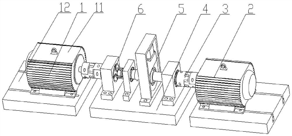
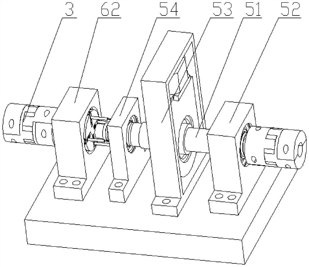
[0043] like figure 1As shown; a device for simulating rolling bearing slipping, including a first power device 1, a second power device 2, a coupling 3 and a fixed seat 4, and the first power device 1 and the second power device 2 are respectively arranged in On both sides of the fixed seat 4, a detection mechanism 5 and an adjustment structure 6 are fixed on the fixed seat 4, and the first power device 1 and the second power device 2 are connected to the first power device 1 and the second power device 2 through a coupling 3 respectively. The power unit 2 is connected, and the first power unit 1 and the second power unit 2 both include an adjustment base 12 and a motor 11 fixed on the adjustment base 12, and the power rod of the motor 11 is connected with the corresponding coupling 3; The adjustment structure 6 includes a speed regulating shaft 61 and a speed regulating seat 62 fixed on the fixed seat 4, one end of the speed regulating shaft 61 is connected with the coupling ...
Embodiment 2
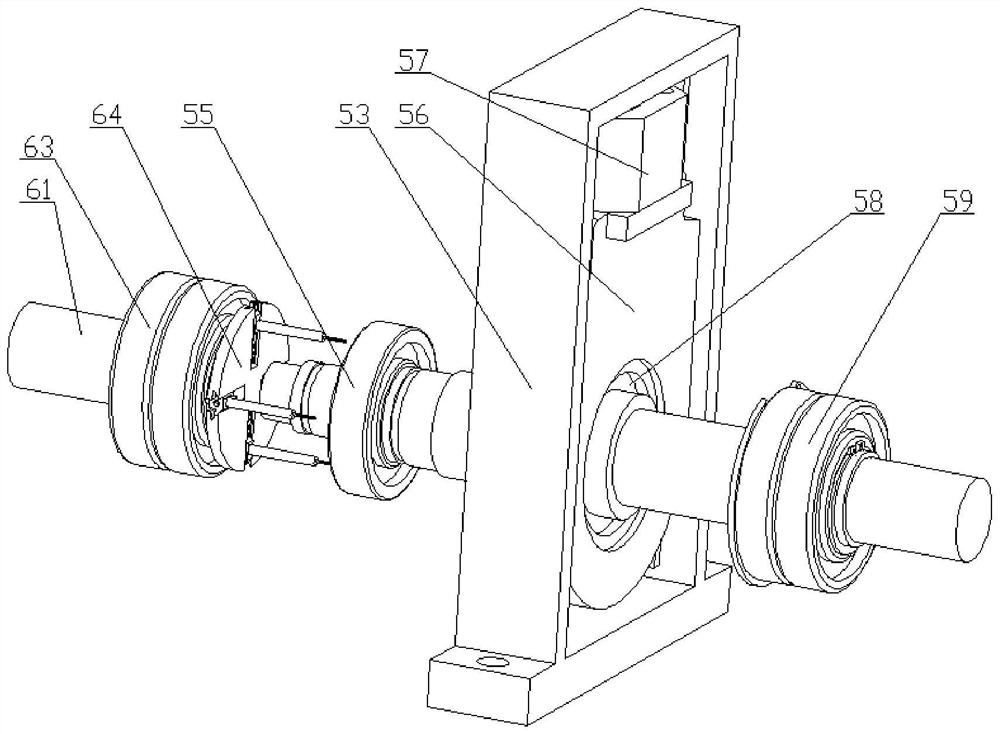
[0046] On the basis of Embodiment 1, one end of the telescopic adjustment rod 610 runs through the dovetail slider 69, the dovetail slider 69 is provided with a stop screw for fixing the telescopic adjustment rod 610, and the dovetail groove 67 is provided with a telescopic adjustment The transition channel 68 through which the rod 610 passes; the coupling 3 is a quincunx type flexible coupling; the motor 11 is a stepping motor; a locking cover 614 and a locking cover 614 are also included. Locking block 613, one end of the telescopic adjusting rod 610 is provided with an external thread that engages with the locking cover 614, the locking cover 614 is provided with a waist-shaped adjusting hole 615, and one end of the stud 611 passes through the waist The type adjustment hole 615 is connected with the locking block 613; a pressure sensor is provided between the hydraulic cylinder 57 and the lifting block 56; a slide rail is connected to the lifting block 56, and the slide rail...
Embodiment 3
[0049] On the basis of Embodiment 2, the end of the test shaft 51 close to the adjustment structure 6 is provided with a stepped shaft; it also includes a fixed ring 510, which is sleeved outside the test shaft 51, and the fixed ring 510 is provided with There is a locking break slot 511, and a locking pin is arranged in the lock break slot 511.
[0050] Install test bearings 55 of different diameters through the stepped shaft, install some larger test bearings 55 through the fixed ring 510, set the fixed ring 510 on the test shaft 51, and set the test bearing 55 on the fixed ring 510 to achieve installation. At the same time, the purpose of fixing the detection bearing 55 and the fixed ring 510 is achieved by inserting the locking pin into the locking broken groove 511.
PUM
 Abstract
Description
Claims
Application Information
PatSnap Eureka turns technology decisions into work you can execute. Powered by our Innovation Knowledge Graph, it runs expert workflows across engineering, life sciences, materials and intellectual property. Get your review-ready output in minutes.


