
Vein verification device based on computer

A verification device and computer technology, applied in computer parts, calculations, instruments, etc., can solve the problems of inability to adjust the height of use, shortened life, poor flexibility, etc., to improve flexibility and firmness, improve safety, and improve stability. sexual effect

Pending Publication Date: 2021-01-12
GUANGZHOU HEDY COMPUTER CO LTD
View PDF0 Cites 1 Cited by
  • Summary
  • Abstract
  • Description
  • Claims
  • Application Information

AI Technical Summary

Problems solved by technology

[0004] The purpose of the present invention is to provide a computer-based vein verification device, which aims to improve the existing finger vein verification devices embedded in door locks, embedded in mice and other products, which must be used in specific scenarios, and there is no one that can be directly integrated with other products. When the device is connected, it can be used in combination with other devices to realize the function of identity verification. The finger vein verifier uses a single-sided light source to irradiate the knuckles of the finger, and then takes an image of the finger vein through the detection head set on the opposite side of the light source. However, the image of the finger vein captured in this way is not clear, which affects the accuracy of verification. At the same time, most of the existing finger vein verifiers are fixedly connected, and the use height cannot be adjusted according to the use requirements. The flexibility of use is poor, and the lack of protective devices is easy to cause damage and shorten the service life of the problem

Method used


Image

  • Vein verification device based on computer
  • Vein verification device based on computer
  • Vein verification device based on computer

Examples


Embodiment Construction

[0032]In order to make the purpose, technical solutions and advantages of the embodiments of the present invention clearer, the technical solutions in the embodiments of the present invention will be clearly and completely described below in conjunction with the accompanying drawings in the embodiments of the present invention. Obviously, the described embodiments It is some embodiments of the present invention, but not all of them. Based on the implementation manners in the present invention, all other implementation manners obtained by persons of ordinary skill in the art without creative efforts fall within the protection scope of the present invention. Accordingly, the following detailed description of the embodiments of the invention provided in the accompanying drawings is not intended to limit the scope of the claimed invention, but merely represents selected embodiments of the invention. Based on the implementation manners in the present invention, all other implementa...


PUM


Abstract

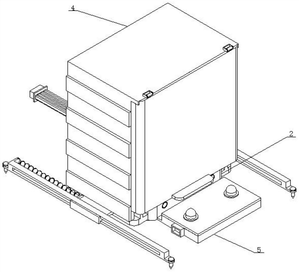
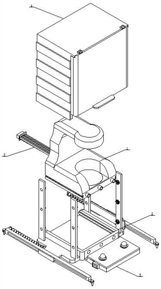
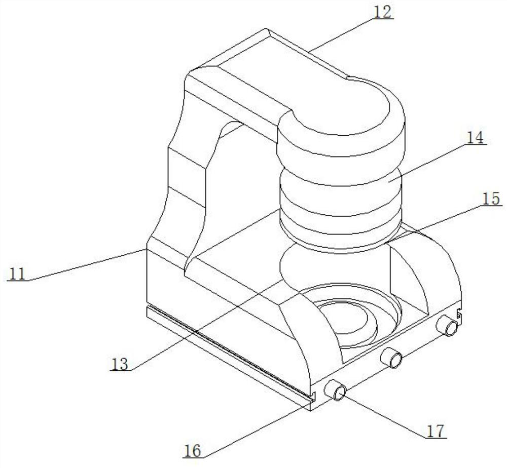
Disclosed is a vein verification device based on a computer comprising a verification machine body, the verification machine body comprises a machine base and an upper lamp holder, the upper lamp holder is vertically welded to the top face of the machine base, a finger groove is vertically formed in the top face of the machine base, and light source lamps are installed at the bottom end of the upper lamp holder and in the finger groove of the machine base; a perspective plate is horizontally bonded to the top end of the finger groove of the machine base, a clamping frame base is installed at the bottom of the machine base, an inserting groove opening is formed in the rear end face of the machine base, a connecting wire is inserted into the inserting groove opening, supporting structures are symmetrically and vertically arranged on the two sides of the clamping frame base, protection structures are installed on the supporting structures, and an electromechanical box is horizontally connected to the front end face of the clamping frame base. Two-way light source irradiation can be conducted on finger veins, so that the shooting definition of the finger veins is improved, later connection with a computer is facilitated, the use convenience is improved, the use height can be adjusted according to use requirements, the use flexibility is good, the device is protected, damage is reduced, and the service life is prolonged.

Description

technical field [0001] The invention relates to the technical field of vein verification, in particular to a computer-based vein verification device. Background technique [0002] Finger vein recognition technology is based on the fact that the blood flowing in human fingers absorbs light of a specific wavelength. Using near-infrared light to irradiate fingers can be based on the absorption of near-infrared light by hemoglobin. However, the existing finger vein verification device Products such as embedded door locks and embedded mice must be used in specific scenarios. There is no product that can be directly connected to other devices, and can be used in combination with other devices to realize the function of identity verification. The finger vein authenticator adopts A single-sided light source is irradiated on the knuckle of the finger, and then the image of the finger vein is captured by the detection head set on the opposite side of the light source. However, the ima...

Claims


Application Information

Patent Timeline
Patent Type & Authority Applications(China)
IPC IPC(8): G06K9/00
CPCG06V40/10G06V40/14
Inventor 陈国庆符张发刘晓强
Owner GUANGZHOU HEDY COMPUTER CO LTD
Learn More