Micro-flow regulator for infusion

A regulator and micro-flow technology, which is applied in the field of medical appliances, can solve the problems of inability to accurately adjust the size of the flow, uneven patient volume of liquid medicine, and inability to perform micro-flow, etc., so as to reduce material production costs, increase buffering, and facilitate The effect of observation

Pending Publication Date: 2021-01-15
JIANGYIN HOMEN RUBBER PLASTIC PROD
View PDF5 Cites 0 Cited by
  • Summary
  • Abstract
  • Description
  • Claims
  • Application Information

AI Technical Summary

Problems solved by technology

[0002] The flow regulator used in ordinary infusion sets is usually sleeved on the outside of the infusion hose, relying on the pressure wheel that gradually approaches and compresses the infusion hose to control the cross-sectional area inside the infusion hose to adjust the flow rate, but This kind of regulator cannot adjust the micro-flow rate. In addition, this kind of regulator does no

Method used


Image

  • Micro-flow regulator for infusion
  • Micro-flow regulator for infusion
  • Micro-flow regulator for infusion

Examples


Example Embodiment

[0021] Example 1

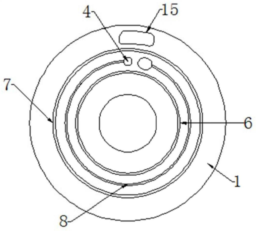
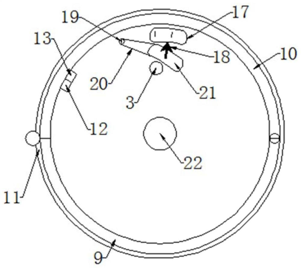
[0022] like Figure 1 to Figure 3 As shown, a micro-flow regulator for infusion, including an upper regulating piece 1, a sealing gasket and a lower regulating piece 2 connected in sequence, the upper regulating piece and the lower regulating piece are coaxially connected and relatively rotated; the upper regulating piece, the lower regulating piece The liquid inlet joint 3 and the liquid outlet joint communicated with the infusion tube, and the liquid inlet through hole 4 and the liquid outlet through hole 5 respectively communicated with the joint are respectively provided. Clamping surface; the lower bottom surface of the upper regulating piece has an inner closed annular protrusion 6 and an outer closed annular protrusion 7, and a C-shaped guide groove 8 is arranged between the inner closed annular protrusion and the outer closed annular protrusion, so that The bottom surface of the diversion groove transitions smoothly from shallow to deep, and the dee...

Example Embodiment

[0029] Example 2

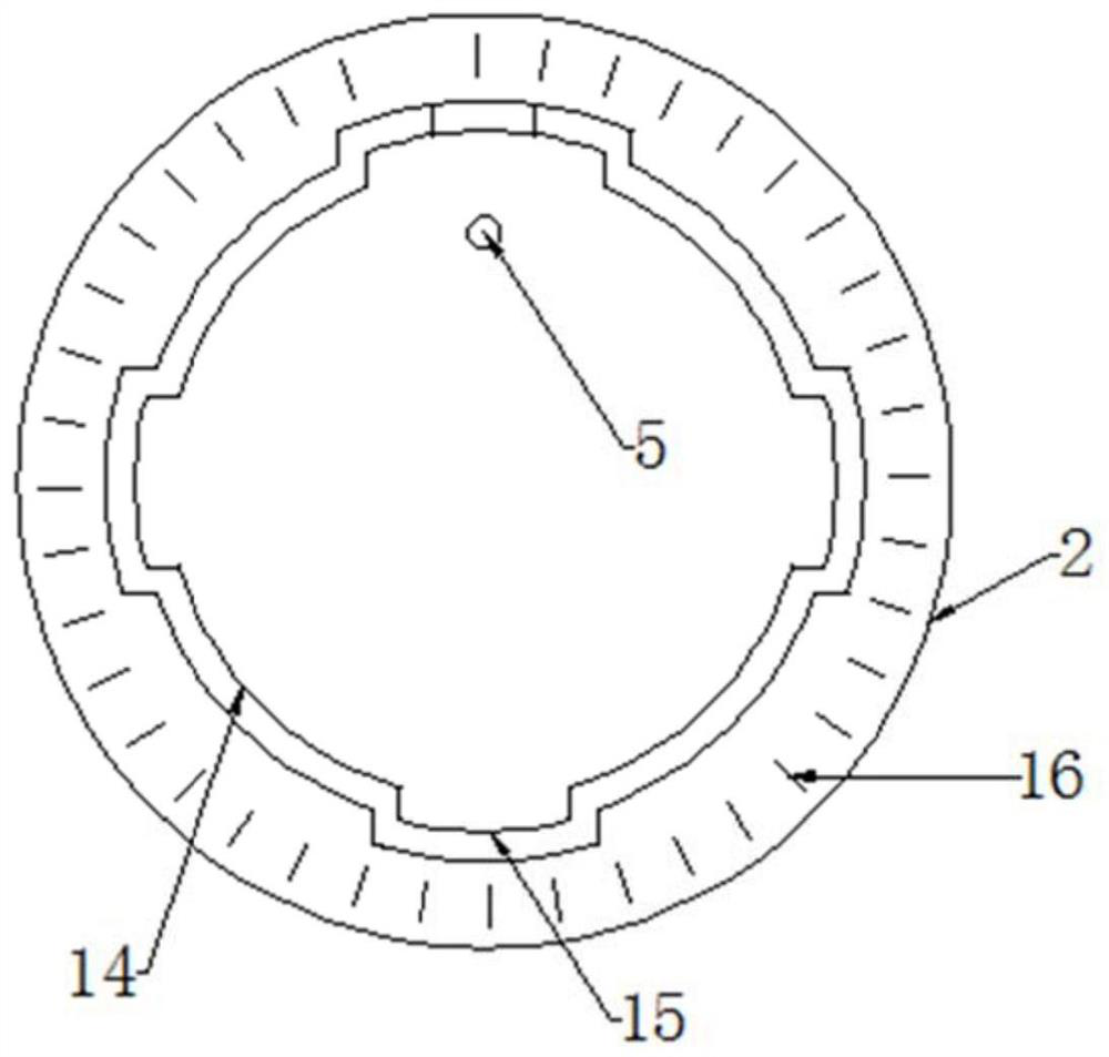
[0030] like Figure 4 , Figure 5 As shown, the difference between Embodiment 2 and Embodiment 1 is that at least three claws 23 are provided on the outer side of the upper regulating piece 1 in the circumferential direction, and the outer side of the lower regulating piece 2 is provided with the claws and can An annular groove 24 for the sliding rotation of the claws. An annular sealing ring 25 is provided on the outer wall of the lower regulating piece above the annular groove.

[0031]A C-shaped diversion groove is provided between the inner closed annular protrusion and the outer closed annular protrusion of the lower bottom surface of the upper regulating piece of the micro-flow regulator of the present invention, and the bottom surface of the C-shaped diversion groove transitions smoothly from shallow to deep, C The deepest part of the tail end of the shaped diversion groove is the liquid inlet hole on the upper regulating piece; the sealing gasket ...


PUM


Abstract

The invention discloses a micro-flow regulator for infusion. The micro-flow regulator for infusion comprises an upper regulating piece, a sealing gasket and a lower regulating piece which are connected in sequence, wherein the upper regulating piece and the lower regulating piece are coaxially connected through a hoop structure arranged on the outer circumference in a sleeving mode and rotate relatively; the upper regulating piece and the lower regulating piece are provided with a liquid inlet connector, a liquid outlet connector, a liquid inlet through hole and a liquid outlet through hole respectively, wherein the liquid inlet connector and the liquid outlet connector communicate with an infusion tube, the liquid inlet through hole and the liquid outlet through hole communicate with theconnectors respectively, and a clamping surface is formed between the lower bottom surface of the upper regulating piece and the upper end surface of the lower regulating piece; and an inner closed annular bulge and an outer closed annular bulge are arranged on the lower bottom surface of the upper regulating piece, a C-shaped flow guide groove is formed between the inner closed annular bulge andthe outer closed annular bulge, the bottom surface of the flow guide groove is in smooth transition from shallow to deep, and the liquid inlet through hole in the upper regulating piece is formed in the deepest position of the tail end of the flow guide groove. A whole infusion channel is composed of the upper regulating piece, the lower regulating piece and the C-shaped flow guide groove with thebottom surface in smooth transition from shallow to deep, and the micro-flow regulator for infusion is reasonable in structure, and can conduct micro-regulation and accurate regulation.

Description

technical field [0001] The invention relates to the technical field of medical appliances, in particular to a micro-flow regulator for infusion. Background technique [0002] The flow regulator used in ordinary infusion sets is usually sleeved on the outside of the infusion hose, relying on the pressure wheel that gradually approaches and compresses the infusion hose to control the cross-sectional area inside the infusion hose to adjust the flow rate, but This kind of regulator cannot adjust the micro-flow rate. In addition, this kind of regulator does not have a flow rate scale, so it cannot accurately adjust the flow rate. At the same time, this kind of regulator will continue to flow with the advancement of time. When the position of the roller is moved, the flow rate of the medicinal liquid gradually increases, and the amount of the medicinal liquid entering the patient's body is uneven, which may cause serious medical accidents to the patient. Contents of the inventio...

Claims


Application Information

Patent Timeline
IPC IPC(8): A61M5/175
CPCA61M5/16813A61M5/16881A61M2205/3331A61M2205/585
Inventor 吴红清
Owner JIANGYIN HOMEN RUBBER PLASTIC PROD
Why Eureka
Try Eureka