Camera cover machining clamp

A camera and fixture technology, used in manufacturing tools, metal processing equipment, metal processing mechanical parts, etc., can solve problems such as camera cover exposure

Active Publication Date: 2021-01-15
宁波星源卓镁技术股份有限公司
View PDF8 Cites 0 Cited by
  • Summary
  • Abstract
  • Description
  • Claims
  • Application Information

AI Technical Summary

Problems solved by technology

[0005] In view of the above-mentioned related technologies, the inventor believes that after removing the process pressure point, the camera cover has the defect of "exposing the bottom" phenomenon

Method used


Image

  • Camera cover machining clamp
  • Camera cover machining clamp
  • Camera cover machining clamp

Examples


Embodiment 1

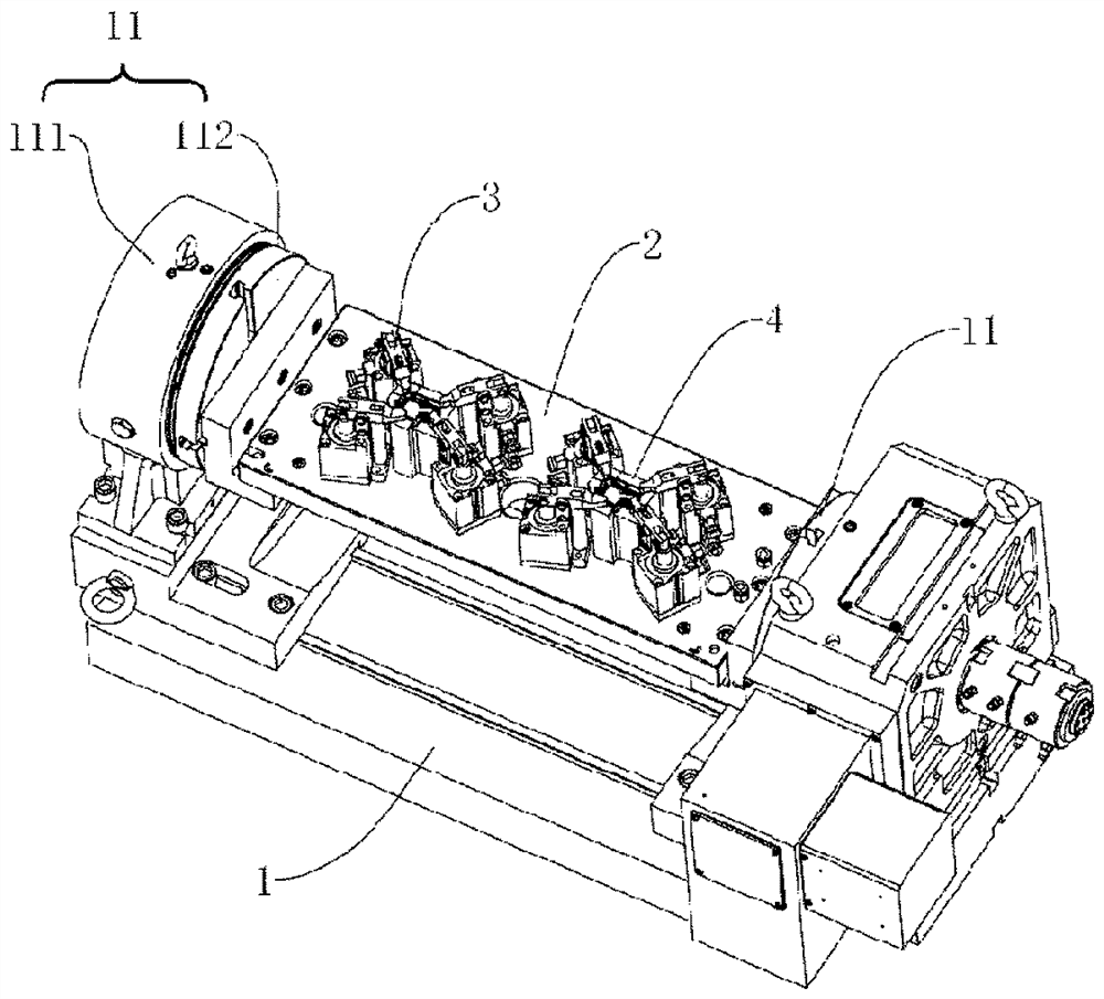
[0042] refer to figure 1 , the camera cover processing jig includes a machine table 1, a rotating seat 11, a driving mechanism, a support plate 2, a pressing assembly 3 and a positioning block 4, the rotating seat 11 is slidably connected with the machine table 1, and the rotating seat 11 includes a seat body 111 and a seat body 111 rotates the connected turntable 112, the turntable 11 is arranged at both ends of the support plate 2 and the turntable 112 and the support plate 2 are connected by bolts. The driving mechanism includes a motor, and the motor is used to drive a turntable 112 to rotate.

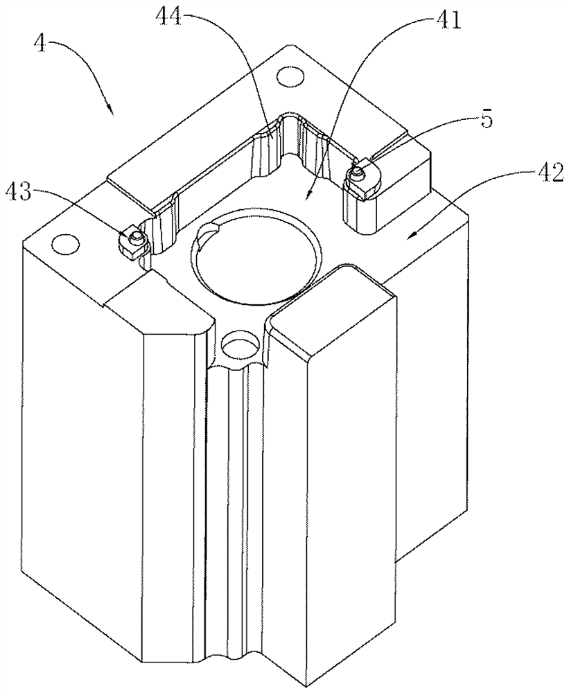
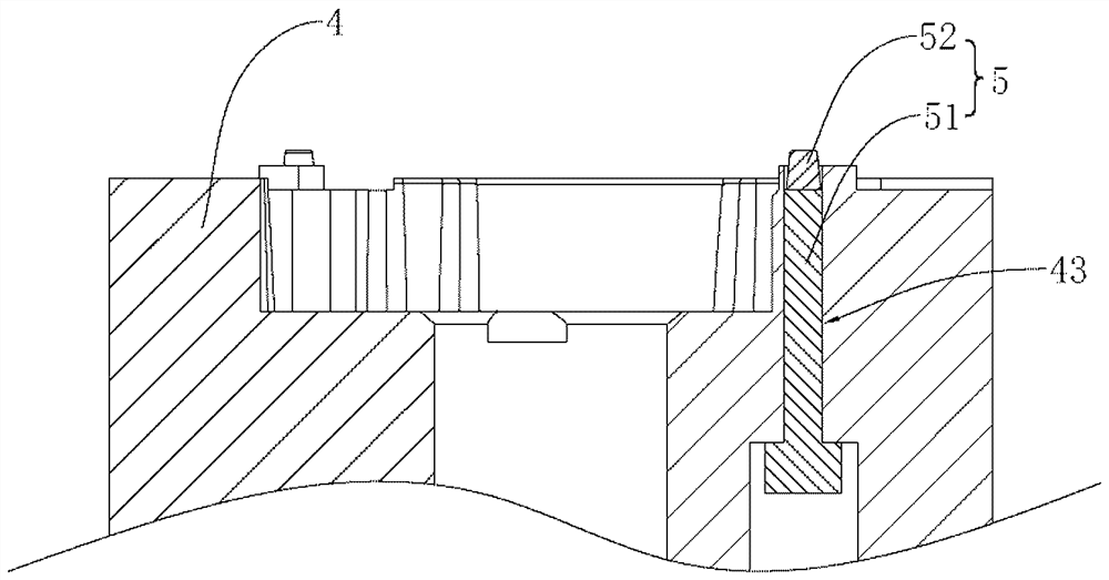
[0043] refer to figure 1 with figure 2 , the positioning block 4 is installed on the support plate 2 through bolts. In this embodiment, there are four groups of pressing components 3 and they are respectively located around the positioning block 4. The positioning block 4 is provided with a positioning cavity 41 for placing the camera cover. Positioning A limiting block 44 is a...

Embodiment 2

[0047] refer to Figure 5 with Image 6 The difference between this embodiment and Embodiment 1 is that the pressing assembly 3 includes a pressing plate 31 and an oil cylinder 32 for driving the pressing plate 31 up and down. The pressing plate 31 includes a plate body 312 and pressing teeth 313. The pressing teeth 313 are used to press the camera cover. The plate body 312 and the pressing teeth 313 are integrally formed. of the circumferential surface. The piston rod of the oil cylinder 32 is rotationally connected to the plate body 312 through a thrust roller bearing.

[0048] refer to Figure 5 with Image 6 , the drive assembly also includes a power part, the power part includes a rotating wheel 71, a motor and a reducer connected to the motor, the motor and the reducer form a power source 72 that drives the rotating wheel 71 to rotate. The rotating wheel 71 includes a circular plate 711 and vertical rods 712 arranged on the circular plate 711 . The circular plate 71...


PUM


Abstract

The invention relates to the field of clamps, in particular to a camera cover machining clamp. The camera cover machining clamp comprises a supporting plate, wherein a pressing assembly is arranged onthe supporting plate. The pressing assembly comprises a driving assembly and a pressing plate used for pressing a camera cover, wherein the driving assembly is connected with the pressing plate and used for driving the pressing plate to move, and when a tool bit moves to the pressing plate, the driving assembly drives the pressing plate to move so that the tool bit can machine the area pressed bythe pressing plate. The camera cover machining clamp has the effect of being capable of avoiding the phenomenon that the camera cover is exposed out of the bottom.

Description

technical field [0001] The present application relates to the field of jigs, in particular to a jig for processing a camera cover. Background technique [0002] At present, when producing camera covers, it needs to go through steps such as die casting, deburring, black anodizing and finishing. [0003] When die-casting a camera cover, usually multiple process pressure points are die-cast on the camera cover. When the camera cover is processed by the cutter head, the pressing component presses the process pressure point, so as to fix the camera cover. [0004] After the processing of the camera cover is completed, the process pressure points need to be removed. That is, the process pressure point is removed from the camera cover by cutting. [0005] In view of the related technologies mentioned above, the inventor believes that after the process pressure point is removed, the camera cover has the defect of "exposing the bottom". Contents of the invention [0006] In ord...

Claims


Application Information

Patent Timeline
Patent Type & Authority Applications(China)
IPC IPC(8): B23Q3/08B23Q1/25
CPCB23Q1/25B23Q3/082
Inventor 邱卓雄谢胜川
Owner 宁波星源卓镁技术股份有限公司
Why Eureka
Try Eureka