Automatic assembly process for electrical cabinet

A technology for automatic assembly and electrical cabinets, applied in manufacturing tools, workpiece clamping devices, etc., can solve the problems of use impact, increase labor intensity of workers, reduce the work efficiency of electrical cabinet assembly operations, etc., to improve work efficiency and reduce labor costs. The effect of workload

Inactive Publication Date: 2021-01-15
JIANGSU JIANXIONG ELECTRIC CO LTD
View PDF0 Cites 4 Cited by
  • Summary
  • Abstract
  • Description
  • Claims
  • Application Information

AI Technical Summary

Problems solved by technology

[0002] Electric cabinets are usually spliced ​​and assembled with bakelite boards to protect the normal operation of components. When assembling and splicing electrical cabinets, each piece of bakelite board needs to be positioned to avoid defective products caused by excessive dimensional assembly errors. However, the existing electrical cabinets have the following problems when assembling and splicing operations. a. When assembling traditional electrical cabinets, the bottom plate of the electrical cabinet is usually placed on the workbench manually, and then the other parts of the electrical cabinet are manually placed on the workbench. The boards are installed and fixed, and the electrical cabinet needs to assemble more boards, often requiring multiple workers to work together to complete the positioning and assembly of the boards. This method of operation increases the labor intensity of the workers and reduces the assembly of the electrical cabinet. The working efficiency of the operation, and the size of the board is usually wide, manual positioning is difficult to ensure that the assembly error between the board surfaces is within a reasonable range, which will affect the later use; b, when the existing electrical cabinet is assembled, it is difficult to Multiple panels are assembled and positioned at the same time, and it is difficult to clamp and fix the panels before assembly, let alone automatically release the clamping operation on the electrical cabinet panels after the assembly operation is completed, which is convenient for manual removal

Method used


Image

  • Automatic assembly process for electrical cabinet
  • Automatic assembly process for electrical cabinet
  • Automatic assembly process for electrical cabinet

Examples


Embodiment Construction

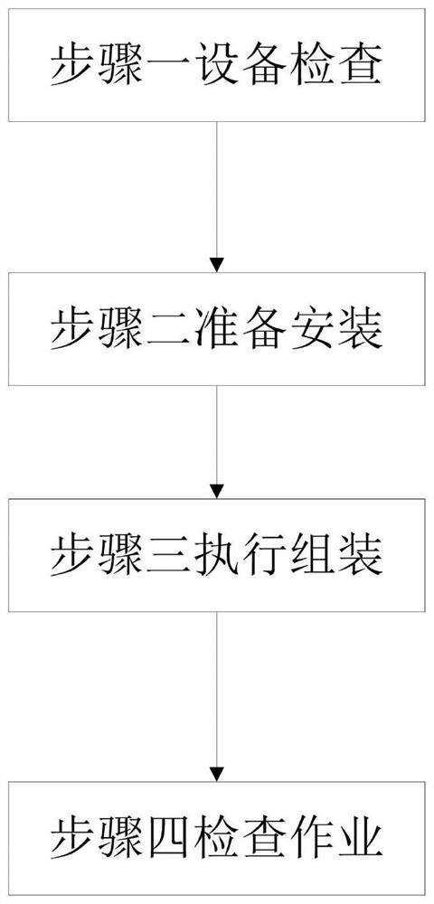
[0031] In order to make the technical means realized by the present invention, creative features, goals and effects easy to understand, the following combination Figure 1 to Figure 9 , to further elaborate the present invention.

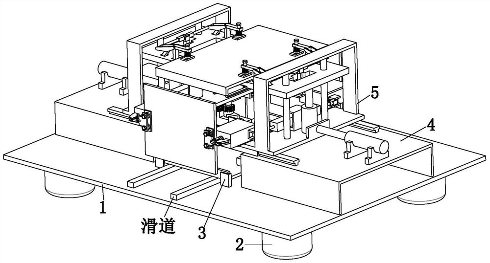
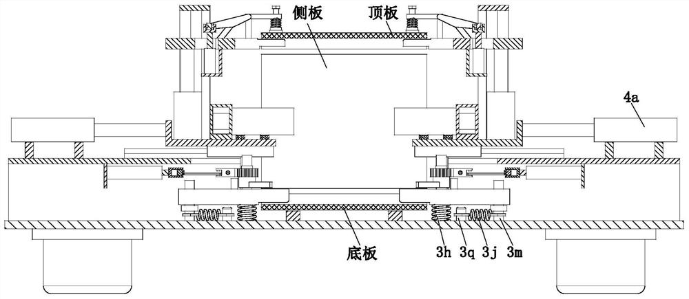
[0032] An automatic assembly process for an electrical cabinet, which uses an auxiliary assembly device, the device includes a mounting base 1, a support foot 2, a positioning mechanism 3, an assembly mechanism 4 and a limit mechanism 5, and the corners around the lower end of the mounting base 1 are The supporting feet 2 are evenly installed at each position, and the upper end of the installation base plate 1 is symmetrically provided with slideways. The installation base plate 1 located on both sides of the slideway is symmetrically installed with a positioning mechanism 3 through sliding fit, and an assembly mechanism is installed on the positioning mechanism 3 through sliding fit. 4, and the assembly mechanism 4 is located above the positioning me...


PUM


Abstract

The invention provides an automatic assembly process for an electrical cabinet, which uses auxiliary assembly equipment. The equipment is provided with a bottom plate, support legs, a positioning mechanism, an assembly mechanism and a limiting mechanism. The invention solves the problems that a bottom plate of an electrical cabinet needs to be manually placed on a workbench during electrical cabinet assembly and fixing operation, then other plates of the electrical cabinet are manually mounted and fixed, the electrical cabinet needs a large number of plates to be assembled, positioning and assembling operation of the plates can be completed only through cooperative operation of a plurality of workers, the labor intensity of the workers is increased through the operation mode, the working efficiency of electrical cabinet assembling operation is reduced, and meanwhile, a plurality of plates are difficult to assemble and position at the same time, the plates are also difficult to clamp and fix before assembly, and the clamping operation of the plates of the electrical cabinet cannot be automatically relieved after the assembly operation is completed.

Description

technical field [0001] The invention relates to the technical field of electrical cabinet assembly, in particular to an automatic assembly process of an electrical cabinet. Background technique [0002] Electric cabinets are usually spliced ​​and assembled with bakelite boards to protect the normal operation of components. When assembling and splicing electrical cabinets, each piece of bakelite board needs to be positioned to avoid defective products caused by excessive dimensional assembly errors. However, the existing electrical cabinets have the following problems when assembling and splicing operations. a. When assembling traditional electrical cabinets, the bottom plate of the electrical cabinet is usually placed on the workbench manually, and then the other parts of the electrical cabinet are manually placed on the workbench. The boards are installed and fixed, and the electrical cabinet needs to assemble more boards, often requiring multiple workers to work together t...

Claims


Application Information

Patent Timeline
Patent Type & Authority Applications(China)
IPC IPC(8): B25B11/02
CPCB25B11/02
Inventor 陈烨周勇周建
Owner JIANGSU JIANXIONG ELECTRIC CO LTD
Why Eureka
Try Eureka