Automatic fiber laying system and planning method for its laying track

A laying trajectory and motion trajectory technology, which is applied in the field of automatic fiber laying system and its laying trajectory planning, can solve the problems of unstudied parameter coupling, few studies on laying pressure/position hybrid control, etc. Poor force, avoid wire/pipe entanglement and motion interference, overcome the effect of laying deviation

Active Publication Date: 2022-02-01
WUHAN UNIV
View PDF18 Cites 0 Cited by
  • Summary
  • Abstract
  • Description
  • Claims
  • Application Information

AI Technical Summary

Problems solved by technology

[0003] At present, there are many studies on the automatic laying system and its control at home and abroad. The design of the robot automatic laying machine mainly focuses on the ability to complete the laying requirements of automatic laying. There are few studies on the mixed control of laying pressure / position, and no Study the influence of parameter coupling (such as: tension-velocity coupling) on ​​the control effect

Method used


Image

  • Automatic fiber laying system and planning method for its laying track
  • Automatic fiber laying system and planning method for its laying track
  • Automatic fiber laying system and planning method for its laying track

Examples


Embodiment Construction

[0036] The present invention will be further described in detail below in conjunction with the accompanying drawings, so that those skilled in the art can implement it with reference to the description.

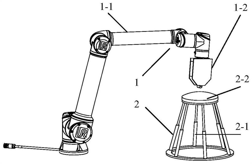
[0037] The invention provides a fiber automatic laying device, such as figure 1 As shown, it includes an automatic fiber placement device 1 based on a collaborative robot arm, a mold carrying device 2 based on a multi-degree-of-freedom motion platform, and a control subsystem for controlling the automatic fiber placement device 1 and the mold carrying platform 2 . Wherein, the automatic fiber placement device 1 includes a cooperative robot arm 1-1 and a placement head 1-2 arranged at the end of the cooperative robot arm 1-1. The mold carrying device 2 includes a multi-degree-of-freedom motion platform 2-1 and an intelligent temperature-controlled mold 2-2 arranged on the multi-degree-of-freedom motion platform 2-1, wherein the laying head 1-2 and the intelligent temperature-c...


PUM


Abstract

The invention discloses an automatic fiber placement system, which includes an automatic fiber placement device, a mold bearing device corresponding to the fiber automatic placement device, and a control subsystem. The control subsystem includes a fiber automatic placement device Controlled press roller pressure-laying track mixing control module and laying tension-speed decoupling control module and temperature fuzzy adaptive control module controlling the temperature of the mold carrying device; the present invention also provides the above-mentioned fiber automatic laying The planning method of the laying track of the laying device. The present invention can realize the precise control of the laying process parameters, thereby improving the laying quality. The laying track of the present invention can make the collaborative manipulator avoid singular poses, and at the same time improve the stress on the joints of the cooperative manipulator, avoid interference, and improve movement efficiency and safety.

Description

technical field [0001] The invention relates to the technical field of laying composite materials. More specifically, the present invention relates to an automatic fiber laying system and a planning method for its laying trajectory. Background technique [0002] Carbon fiber composite materials have excellent properties such as high specific strength, high specific modulus, fatigue resistance and chemical corrosion resistance, and are widely used in aerospace, automobile, ship and sports equipment and other fields. Automatic lay-up technology is one of the important methods to achieve composite molding. According to the shape of fiber reinforced composite materials, automatic laying technology can be divided into two types: automatic tape laying and automatic wire laying. The automatic laying technology combines the advantages of automatic tape laying and fiber winding technology. The laying head combines the independent conveying of multiple prepreg tows in the winding te...

Claims


Application Information

Patent Timeline
Patent Type & Authority Patents(China)
IPC IPC(8): B29C70/38B29C70/54
CPCB29C70/384B29C70/54
Inventor 肖晓晖段宝阁陆伟杨尚尚何思宇王镇李正顺
Owner WUHAN UNIV
Why Eureka
Try Eureka