

Siphon end structure for steam heating roller
A technology of end structure and siphon tube, which is applied in the field of siphon tube end structure for steam heating rollers, and can solve problems such as inability to locate, high processing and manufacturing costs, and increasing the design gap of siphon tubes.
Pending Publication Date: 2021-01-15
抚顺东旭精工制辊科技有限公司
View PDF0 Cites 1 Cited by
- Summary
- Abstract
- Description
- Claims
- Application Information
AI Technical Summary
Problems solved by technology
[0008] The most common condensate siphon system for steam heating rollers mainly includes two parts: a rotary joint and a siphon pipe. It can be directly installed on the end of the roller, or can be installed on the end of the roller through the threaded connection hole processed at the end of the shaft head, or can be installed on the end of the roller through a flange; the siphon is usually made of ordinary steel pipe, The front end is formed into an elbow by progressive bending, and the end is installed on the rotary joint by screw fastening; the traditional elbow condensate siphon system has always been, and even today, still the most common and most commonly used condensate water system in the market The advantages of the siphon system are: the siphon is usually made of ordinary steel pipe, which is simple to process, easy to manufacture, low in cost, easy to install and disassemble, and can meet or basically meet the needs of corrugating machines, and even most corrugating machines at present; the disadvantages are:
It is worth noting that: the siphon tube is limited by material selection, length and diameter, and it is difficult to carry out precision machining except for the pipe thread at the end position, and there is no other processing except pipe thread and bending at all;
[0010] 2. It is impossible to ensure the siphon gap accurately, reliably and controllably
The traditional elbow type siphon is only installed at the end of the swivel joint or the end cap of the swivel joint without any other supporting structure. Due to the limitation of its length, weight, simple support beam mode and rigidity, it cannot be in the ideal design position at all. In addition to the complex site and actual external factors, the common symptoms are: when the roller is running slowly, the sound of the siphon scraping cavity is often heard. The reason is that the siphon lacks an effective second support positioning structure;
[0011] 3. The vertical position of the elbow cannot be guaranteed reliably, controllably and effectively
It is worth noting that the annular groove has a certain influence on the rigidity of the roller. A large number of examples have proved that the annular groove with a depth of 5mm will have a certain impact on the quality of the cardboard, and the annular groove with a depth of 2.5mm will not, but the The above-mentioned 2.5mm groove is only a theoretical form design, and has no effect on the actual drainage effect
[0014] The advantages of the traditional elbow condensate siphon system are simple structure, easy processing, easy installation and disassembly, and low cost; the disadvantages are uncontrollable, unreliable, unstable, and imprecise, and it is impossible to control the gap between the elbow and the roller cavity, and it is impossible to control The specific position of the elbow
The advantages of the controllable or effective condensate siphon system are: controllable, reliable, stable and precise, it can precisely control the gap between the elbow and the roll cavity, and discharge condensate efficiently; it can effectively lock and control the position of the elbow, without rollers" "banana effect"; the disadvantages are: complex structure, high processing and manufacturing costs, difficult installation and disassembly, inseparable from the necessary technical guidance, and even inseparable from special installation and disassembly tools
[0018] In summary, the external factors for the breakage of the siphon tube or the head of the siphon tube are the fatigue fracture caused by the impact of the high-speed running roller for a long time without interruption. There are two general directions for the solution of the problem, one is to increase the size of the siphon tube Self-strength, but its temporary solution does not cure the root cause. Even the one-piece siphon can be impacted to fatigue fracture, and then take a step back. If the siphon is strong enough, it is the turn of the rotary joint or the support sleeve to break; the second is to increase the size of the siphon. The design gap, the siphon tube will not be broken due to the impact of external force, but this will cause another bigger problem, the design gap is large, the water ring generated when the roller is running is thickened, and the heat conduction efficiency of the roller is low. The "banana effect" of the roller appears, which is a technical dilemma
Method used
View moreImage
Smart ImageViewing Examples

Examples
Embodiment approach ( 1
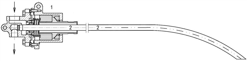
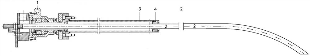
[0034] Preferred implementation mode (1): suitable for bent or inclined tube siphons: 1. End wall thickness removal processing; 2. Bending; 3. Further processing of end structure.
Embodiment approach ( 2
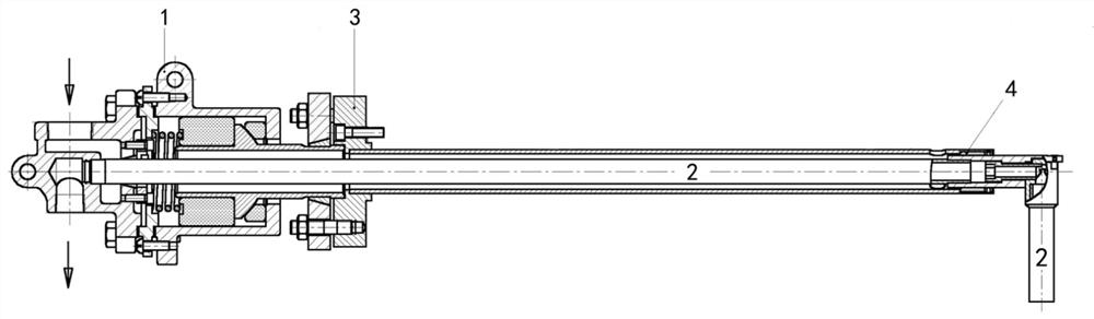
[0035] Preferred implementation mode (2): suitable for straight pipe siphon: 1. Design the siphon gap of the siphon to be 2 mm; 2. Remove the wall thickness for processing.
Login to View More PUM
 Abstract
The invention discloses a siphon end structure for a steam heating roller, belongs to the field of machinery, and mainly relates to an end structure of a siphon of a condensed water siphon system of the steam heating roller. An inner cavity is arranged in a roller body of the steam heating roller, and the two ends of the roller body are each fixedly connected with a shaft head. One end of each shaft head extends into the roller body, and one shaft head of the roller is of a through hole structure. The siphon end structure is characterized in that the siphon is provided with an end protection structure formed by removing part of wall thickness materials at the end, and the end protection structure can prevent the siphon from being possibly subjected to fatigue impact of the roller for a long time compared with the characteristics of low strength and quick wear relative to other parts of the siphon, so that the technical problem of double difficulties that the minimum siphon gap needs tobe ensured and the siphon is possibly subjected to fatigue impact of the roller in high-speed operation for a long time to cause common breakage is solved.
Description
technical field [0001] The invention belongs to the field of machinery, and mainly relates to a siphon end protection structure of a condensed water siphon system of a steam heating roller. A shaft head is connected and fixed at both ends, and one end of the shaft head extends into the roller body, and one shaft head of the roller is a through-hole structure, such as a corrugated roller and a pressure roller used for heating corrugated cardboard. In the present invention, the corrugated roll is used as a typical steam heating roll to describe the protection structure at the end of the siphon tube. Background technique [0002] Corrugated cartons are the most widely used green packaging products. The corrugated box is made of corrugated cardboard, and the corrugated cardboard is manufactured by the corrugated cardboard production line. The core of the corrugated cardboard production line is the corrugating machine. Cots, and the 5 rollers are typical representative features...
Claims
Login to View More Application Information
Patent Timeline
 IPC IPC(8): B31F1/20F28B9/08
CPCB31F1/20F28B9/08
Inventor 齐凤伟
Owner 抚顺东旭精工制辊科技有限公司