Supercharge Your Innovation With Domain-Expert AI Agents!

Placing structure for elevator

A hoist and rotating mechanism technology, applied in the direction of conveyor objects, transportation and packaging, etc., can solve the problems of time-consuming and labor-intensive, increase the labor load of staff, increase the length of fire extinguisher handling, etc., to improve transfer efficiency and reduce work volume effect

Pending Publication Date: 2021-01-15
HENAN LVBO ENERGY EQUIP CO LTD
View PDF0 Cites 0 Cited by
  • Summary
  • Abstract
  • Description
  • Claims
  • Application Information

AI Technical Summary

Problems solved by technology

[0002] After the fire extinguisher is produced, it needs to be transported out of the production site to the storage site. Due to the particularity of the fire extinguisher, it cannot be shaken or shaken violently. When it is transported, it needs to be carried by hand repeatedly. Manual transport is time-consuming and labor-intensive. Workers need to bend repeatedly Waist and stand up increase the workload of the staff, and workers need to pay more attention to safety, which also increases the handling time of fire extinguishers

Method used


Image

  • Placing structure for elevator
  • Placing structure for elevator
  • Placing structure for elevator

Examples


Embodiment 1

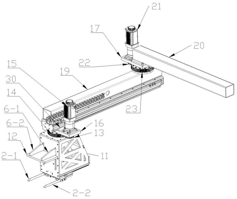
[0026] Such as figure 2 As shown, a placement structure for a hoist includes a material receiving and unloading device and a swing arm device. The swing arm device includes a swing arm rotation mechanism and a forward and backward movement mechanism. The arm member rotates with the swing arm member, and the connecting and unloading device is installed on the forward and backward moving mechanism, and the forward and backward moving mechanism drives the connecting and unloading device to move forward and backward.

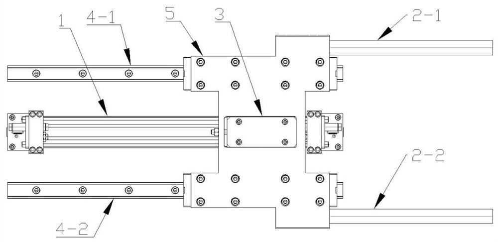
[0027] The receiving and unloading device comprises a support 11, a shoveling mechanism and a rotating mechanism, the shoveling mechanism is installed on the bottom of the support 11, and the rotating mechanism is installed on the top of the support 11, and the shoveling mechanism includes a shoveling power component and a shoveling component, and the shoveling power The shoveling power part of the component is connected to the shoveling component and pushes the sh...

Embodiment 2

[0043] A placement structure for a hoist, which differs from Embodiment 1 in that a hoisting device is added, which facilitates subsequent placement of materials.

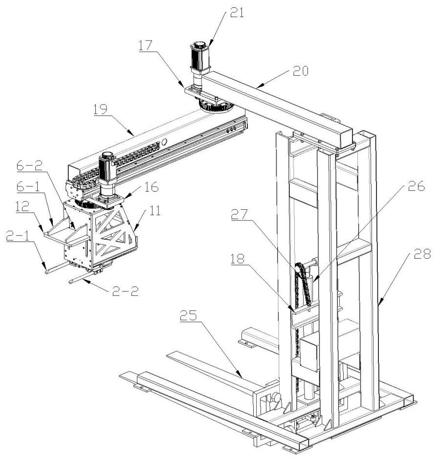
[0044] Such as figure 1 As shown, the lifting device is installed on the support frame I 28, including a lifting power component and a material receiving part, and the lifting power component is connected with the material receiving part and drives the material receiving part to move up and down.

[0045] The lifting power component includes a chain III 27 and an oil cylinder 26, the upper part of the piston rod of the oil cylinder 26 can be provided with a sprocket, the chain III 27 bypasses the sprocket, and the two ends of the chain III 27 are respectively connected with the fixed rod 18 and the material receiving part. Engaged with the sprocket, the chain III27 and the sprocket can also be replaced by belts and pulleys; the piston rod of the oil cylinder 26 moves up and down, driving the chain III27 to move, th...


PUM


Abstract

The invention discloses a placing structure for an elevator. The placing structure comprises a receiving and discharging device and a swing arm device, wherein the swing arm device comprises a swing arm rotating mechanism and a front-and-back moving mechanism, the front-and-back moving mechanism is installed on a swing arm component of the swing arm rotating mechanism and rotates along with the swing arm component, the receiving and discharging device is installed on the front-and-back moving mechanism, and the front-and-back moving mechanism drives the receiving and discharging device to movefront and back. By arranging the receiving and discharging device for receiving and discharging materials, the swing arm device for transferring the materials and a lifting device for receiving and discharging the materials, the materials can be flexibly placed at a predetermined position, the workload of workers is reduced, and the material transferring efficiency is improved.

Description

technical field [0001] The invention belongs to the technical field of material lifting equipment, and in particular relates to a placement structure for a hoist. Background technique [0002] After the fire extinguisher is produced, it needs to be transported out of the production site to the storage site. Due to the special nature of the fire extinguisher, it cannot be shaken or shaken violently. When it is transported, it needs to be carried by hand repeatedly. Manual transport is time-consuming and labor-intensive. Workers need to bend repeatedly Waist and standing up increase the workload of the staff, and the workers need to pay more attention to safety, which also increases the handling time of the fire extinguisher. Contents of the invention [0003] The technical problem to be solved by the present invention is the inconvenience of transporting the fire extinguisher after production, so as to provide a placement structure for the hoist. [0004] In order to solve...

Claims


Application Information

Patent Timeline
Patent Type & Authority Applications(China)
IPC IPC(8): B65G47/74B65G47/82
CPCB65G47/74B65G47/82
Inventor 孙保定徐科峰
Owner HENAN LVBO ENERGY EQUIP CO LTD
Features
  • R&D
  • Intellectual Property
  • Life Sciences
  • Materials
  • Tech Scout
  • Unparalleled Data Quality
  • Higher Quality Content
  • 60% Fewer Hallucinations
Learn More