Profile steel, profile steel-UHPC composite plate, bridge deck slab and steel-UHPC composite beam bridge

A bridge deck and composite plate technology, applied in bridges, bridge parts, bridge materials, etc., can solve the problems of insufficient tensile capacity of the joint bottom surface, difficult to apply to large-span bridges, increased average plate thickness, etc., and achieves low construction difficulty. , The effect of high rigidity and small pouring amount

Pending Publication Date: 2021-01-15
HUNAN UNIV
View PDF2 Cites 3 Cited by
  • Summary
  • Abstract
  • Description
  • Claims
  • Application Information

AI Technical Summary

Problems solved by technology

However, practice has shown that UHPC low-rib bridge decks are 30% heavier than traditional steel decks, and are still difficult to apply to long-span bridges
In patents CN109338866A and CN109610310A, Professor Shao Xudong proposed a new type of steel-UHPC low-rib plate, but the bridge deck is used in long-span bridges, and there are many transverse wet joints, and a transverse diaphragm needs to be installed. In order to ensure the safety of the joints, the height of the transverse joints is set higher (the sum of the height of the UHPC top plate and the lower section steel), and the width is larger. In the above-mentioned patents, it is generally taken as 300mm, so the pouring volume is relatively large. It leads to an increase in the average plate thickness, which is unfavorable for long-span flexible bridges that are extremely sensitive to their own weight
At the same time, in these two patents, there is insufficient tensile capacity of the bottom surface of the joint in the transverse wet joint. For the mid-span area of ​​the cable-stayed bridge or the negative moment area of ​​the continuous girder bridge, since the bridge deck is in a state of axial tension in the longitudinal direction, Tensile stress at the bottom of the transverse seam, with possible risk of cracking

Method used


Image

  • Profile steel, profile steel-UHPC composite plate, bridge deck slab and steel-UHPC composite beam bridge
  • Profile steel, profile steel-UHPC composite plate, bridge deck slab and steel-UHPC composite beam bridge
  • Profile steel, profile steel-UHPC composite plate, bridge deck slab and steel-UHPC composite beam bridge

Examples


Embodiment 1

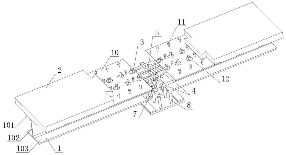
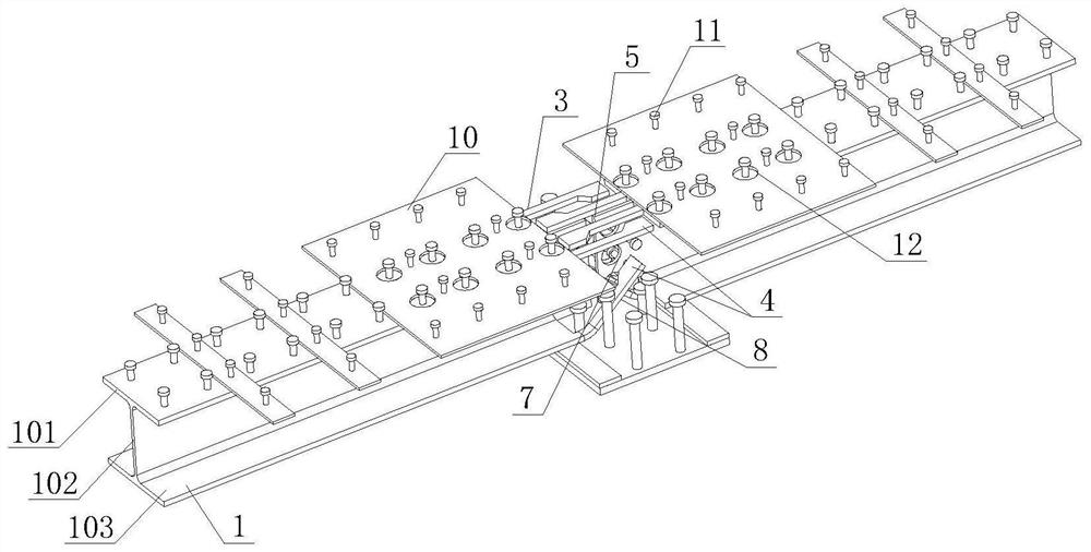
[0057] Such as Figure 1-Figure 8 As shown, the section steel of this embodiment includes an upper flange plate 101, a web 102 and a lower flange plate 103, the upper flange plate 101 is arranged on the top of the web 102, and the lower flange plate 103 is arranged on the bottom of the web 102, The end of at least one of the upper flange plate 101, the web 102 and the lower flange plate 103 extends outwards and is provided with an extension section (in this embodiment, the ends of the upper flange plate 101, the web 102 and the lower flange plate 103 The ends are all extended outwards and provided with extensions); the extensions at the end of the upper flange plate 101 are a plurality of first long straight bars 3 arranged at intervals, and the ends of the first long straight bars 3 are provided with enlarged parts 4 (Such as Figure 1-8 As shown, the shape of the enlarged part 4 is a rectangle with a transition edge); the extension section at the end of the web 102 is an ep...

Embodiment 2

[0069] Such as Figure 20-21 As shown, the section steel of this embodiment includes an upper flange plate 101 and a web 102, the upper flange plate 101 is arranged on the top of the web 102, and the ends of the upper flange plate 101 and the web 102 are all extended outward. Extension section; the extension section at the end of the upper flange plate 101 is a plurality of first long straight bars 3 arranged at intervals, and the end of the first long straight bar 3 is provided with an enlarged part 4; the extension section at the end of the web 102 For the epitaxial steel plate 5 (such as Figure 20 shown) or at least one second long straight strip 6 (such as Figure 21 As shown), the epitaxial steel plate 5 is provided with a plurality of first through holes 7 , and the end of the second long straight bar 6 is provided with an enlarged portion 4 .

[0070] The steel-UHPC composite panel of this embodiment includes a UHPC panel 2 and a plurality of the above-mentioned sect...


PUM


Abstract

The invention discloses profile steel which comprises an upper flange plate and a web plate, and the end of the upper flange plate and/or the end of the web plate extend/extends outwards to form an extending section. The invention further discloses profile steel which comprises an upper flange plate, a web plate and a lower flange plate, and the end of at least one of the upper flange plate, the web plate and the lower flange plate extends outwards to be provided with an extending section. The invention further provides a profile steel-UHPC composite plate which comprises a UHPC plate and a plurality of profile steel, wherein the UHPC plate is arranged on the upper flange plate of the profile steel. The invention further provides a bridge deck slab and a steel-UHPC composite beam bridge. The structure of the end of the profile steel is optimized, and the end of the profile steel is provided with the outer extending section, so that when the profile steel-UHPC composite plate obtained through the profile steel is connected through a wet joint, joint force transmission is more reliable, the tensile capacity is high, rigidity is high, various stress working conditions such as pulling,pressing, bending, shearing and twisting can be borne, and the joint can meet the full-section pulling condition.

Description

technical field [0001] The invention belongs to the field of bridges, and in particular relates to a steel structure for forming a bridge deck, a composite board, a bridge deck and a composite girder bridge. Background technique [0002] Long-span bridges are a symbol of the country's technological level. Steel structure bridges have the advantages of light weight, large spanning capacity, and good seismic performance, and are the first choice for long-span bridges. The deck structure of steel bridges usually adopts orthotropic steel deck system, but because the steel deck is a fully welded structure, not only the cost is high, but also the steel deck system suffers from two major diseases under the action of heavy-duty vehicles: ( 1) Fatigue cracking and local buckling of the steel bridge deck endanger the safety of the bridge; (2) frequent damage to the asphalt pavement and huge renovation costs. The above-mentioned diseases reduce the operating efficiency of bridges and...

Claims


Application Information

Patent Timeline
Patent Type & Authority Applications(China)
IPC IPC(8): E01D1/00E01D19/12E01D101/30
CPCE01D1/00E01D19/125E01D2101/30
Inventor 邵旭东李玉祺曹君辉
Owner HUNAN UNIV
Why Eureka
Try Eureka