Building construction flying dust monitoring device

A monitoring device and building construction technology, applied in measurement devices, instruments, closed-circuit television systems, etc., can solve the problems of easy shaking of monitoring devices, influence of monitoring data, time-consuming and laborious, etc., to prevent the impact of lightning strikes and static electricity, and ensure monitoring data. , to avoid the effect of shaking

Pending Publication Date: 2021-01-15
JINLING INST OF TECH
View PDF10 Cites 2 Cited by
  • Summary
  • Abstract
  • Description
  • Claims
  • Application Information

AI Technical Summary

Problems solved by technology

[0003] During the construction process, it is necessary to monitor the dust. The existing dust monitoring device for construction is not easy to move. When it is necessary to monitor the dust at d

Method used


Image

  • Building construction flying dust monitoring device
  • Building construction flying dust monitoring device
  • Building construction flying dust monitoring device

Examples


Example Embodiment

[0022]Example one

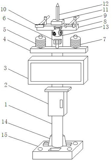
[0023]ReferenceFigure 1-3, A building construction dust monitoring device, including a support rod 1, a waterproof box 2 is fixed on the outer wall of the support rod 1 by bolts, and an LED display 3 is fixed on the outer wall of the support rod 1 by bolts, and the LED display 3 is located in the waterproof box 2 Above, the outer wall of the support rod 1 is fixed with a first fixing rod 4 by bolts. The first fixing rod 4 is located above the LED display 3. The outer walls on both sides of the top of the first fixing rod 4 are respectively fixed with a humidity tester 5 and The temperature tester 7 can monitor the humidity and temperature of the dust in the air. The top outer wall of the first fixing rod 4 is fixed with a decibel tester 6 through bolts. The decibel tester 6 is located between the humidity tester 5 and the temperature tester 7. The top outer wall of the support rod 1 is fixed with a second fixing rod 8 by bolts. The two outer walls of the top of the ...

Example Embodiment

[0024]Example two

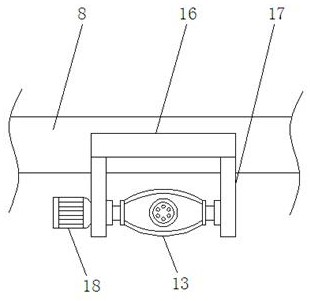
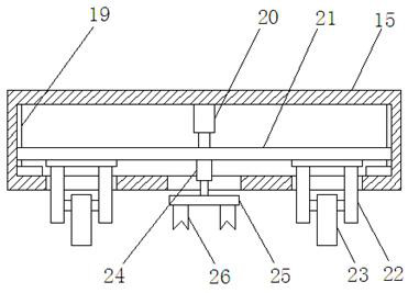
[0025]Referencefigure 1 ,2And 4, a building construction dust monitoring device, comprising a support rod 1, a waterproof box 2 is fixed on the outer wall of the support rod 1 by bolts, and an LED display 3 is fixed on the outer wall of the support rod 1 by bolts. The LED display 3 is located Above the waterproof box 2, the outer wall on one side of the support rod 1 is fixed with a first fixing rod 4 by bolts. The first fixing rod 4 is located above the LED display 3. The outer walls on both sides of the top of the first fixing rod 4 are respectively fixed with humidity testers by bolts. 5 and temperature tester 7, which can monitor the humidity and temperature of the dust in the air. The top outer wall of the first fixing rod 4 is fixed with a decibel tester 6 by bolts. The decibel tester 6 is located between the humidity tester 5 and the temperature tester 7. At the same time, the top outer wall of the support rod 1 is fixed with a second fixing rod 8 by bolts, a...


PUM


Abstract

The invention discloses a building construction flying dust monitoring device which comprises a supporting rod. A waterproof box is fixed to the outer wall of one side of the supporting rod through bolts, an LED display screen is fixed to the outer wall of one side of the supporting rod through bolts, the LED display screen is located above the waterproof box, a first fixing rod is fixed to the outer wall of one side of the supporting rod through bolts, the first fixing rod is located above the LED display screen, and a humidity tester and a temperature tester are fixed to the outer walls of the two sides of the top of the first fixing rod through bolts correspondingly. By arranging an air cylinder, a moving plate, a roller assembly and rollers, the monitoring device can be moved, so thatflying dust of monitoring points at different positions is conveniently monitored, time and labor are saved, by arranging stabilizing feet, a base, an electric telescopic rod, fixing teeth, supportingseats and an anti-skid pad, the monitoring device can be further stabilized, and the shaking phenomenon in the monitoring process is avoided.

Description

Technical field[0001]The invention relates to the technical field of flying dust monitoring, in particular to a building construction flying dust monitoring device.Background technique[0002]Building construction refers to the production activities in the implementation phase of project construction. It is the construction process of various types of buildings. It can also be said that the various lines on the design drawings are turned into physical objects at designated locations.[0003]In the process of building construction, it is necessary to monitor the fugitive dust. The existing fugitive dust monitoring device for building construction is not easy to move. When the fugitive dust at different monitoring points needs to be monitored, it needs to be moved manually, which is time-consuming and labor-intensive. During the process, the monitoring device is easy to shake, which will affect the monitoring data.Summary of the invention[0004]Based on the technical problems existing in t...

Claims


Application Information

Patent Timeline
IPC IPC(8): F16M11/24F16M11/12F16M11/18H04N7/18G01D21/02
CPCF16M11/12F16M11/18F16M11/24G01D21/02H04N7/18
Inventor 张旺李翔陆季军宋昕锐崔璨
Owner JINLING INST OF TECH
Why Eureka
Try Eureka