a flame stabilizer

A flame stabilizer and wall surface technology, which is applied in combustion methods, combustion chambers, combustion equipment, etc., can solve the problems of large temperature difference on the wall surface and affect the wall surface temperature of the flame stabilizer, so as to reduce wall temperature, reduce thermal stress, and facilitate combustion Effect

Active Publication Date: 2022-02-11
NANJING UNIV OF AERONAUTICS & ASTRONAUTICS
View PDF7 Cites 0 Cited by
  • Summary
  • Abstract
  • Description
  • Claims
  • Application Information

AI Technical Summary

Problems solved by technology

In this patent, after cooling through the impact hole + opposite air film hole, the cooling air flowing out of the air film hole forms a vortex air film and adheres to the outer wall of the stabilizer, and the temperature drop of the wall can reach 300K. By controlling the temperature of the wall directly behind the flame stabilizer , which in turn affects the wall temperature of the entire flame holder
However, the cooling effect of this solution on the windward side of the flame stabilizer and the side wall has not yet reached an ideal state, and the temperature difference on the wall is still large

Method used


Image

  • a flame stabilizer
  • a flame stabilizer
  • a flame stabilizer

Examples


Embodiment Construction

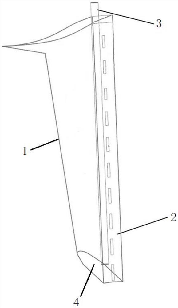
[0028] The flame stabilizer described in the prior art is as figure 1 As shown, it is a hollow cylinder with an open top and a closed bottom end, including a windward wall 1, a rear end wall 2 and a bottom end 4, the windward wall 1 and the rear end wall 2 are connected by a side wall, and the flame is stable An oil injection rod 3 with the same extension direction is also arranged in the device, an outlet 21 is arranged on the rear end wall 2, and the open end of the flame stabilizer communicates with the outer duct.

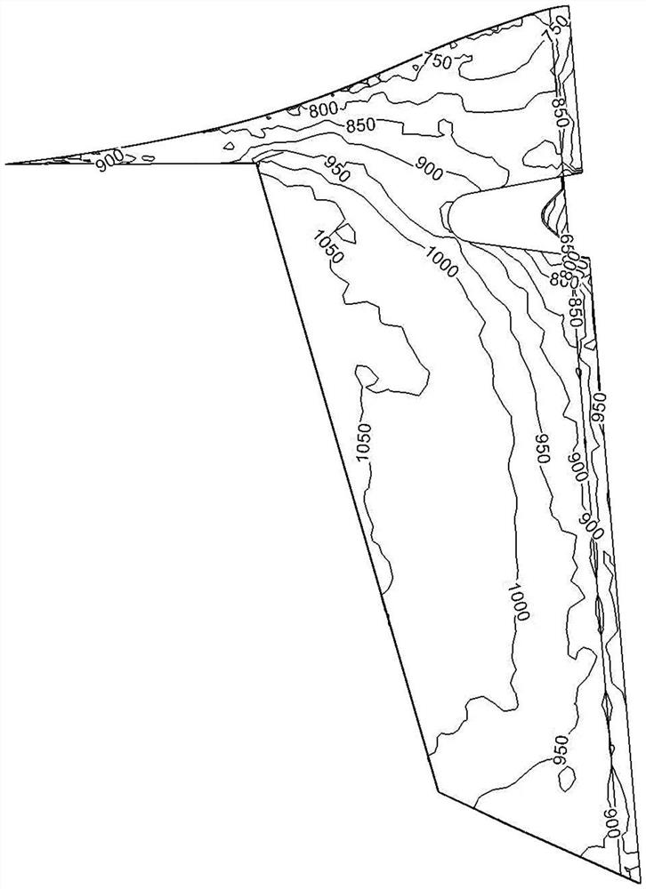
[0029] At this time, the wall temperature contour of the flame holder is as follows: figure 2 As shown in Fig. 1, due to the sudden expansion of the flow channel of the cooling air in the outer channel when it enters the flame holder, a wall-attached separation zone is formed inside the leading edge, and the outer channel cold flow cannot effectively cool the windward side of the flame holder, and the flame is stable. The temperature on the windward side of t...


PUM


Abstract

The invention belongs to the technical field of an integrated design afterburner, and specifically relates to a flame stabilizer, which includes a windward wall, a rear end wall, a bottom end and a cooling structure, the windward wall and the rear end wall are connected through a side wall, The flame stabilizer is also provided with an oil spray rod in the same direction as it extends, the rear end wall is provided with an outlet, and the cooling structure is disposed inside the flame stabilizer, including a deflector and a baffle. Both the deflector and the baffle are facing the incoming flow direction of the cooling air, the deflector includes a windward arc surface and a straight section, the windward arc surface is smoothly connected with the straight section, and the windward arc surface of the deflector The front edge cooling channel is formed between the deflector and the windward wall, the central cooling channel is formed between the deflector and the partition, and the rear cold air cavity is formed between the partition and the rear end wall. The fuel injection rod is located in the rear cold air chamber, and the bottom ends of the front edge cooling passage, the central cooling passage and the rear cold air chamber communicate with each other.

Description

technical field [0001] The invention belongs to the technical field of an integrated design afterburner, and in particular relates to a flame stabilizer. Background technique [0002] In order to increase the thrust of the engine in a short period of time, the way of afterburning is often used. Based on this method, the integrated afterburner developed in accordance with the idea of ​​reducing flow loss, shortening the length of the combustion chamber, and improving work reliability is an important direction of engine development. Whether the flame stabilizer in the integrated afterburner can work normally under high temperature conditions is an important factor affecting the stability of modern engines, and how to ensure that the wall temperature of the flame stabilizer is within the range that the material can withstand , is an urgent problem to be solved. [0003] The existing patent publication number is the invention patent of CN105650677A, which discloses a flame sta...

Claims


Application Information

Patent Timeline
Patent Type & Authority Patents(China)
IPC IPC(8): F23R3/20
CPCF23R3/20
Inventor 单勇贾翔中张靖周谭晓茗
Owner NANJING UNIV OF AERONAUTICS & ASTRONAUTICS
Why Eureka
Try Eureka