Supercharge Your Innovation With Domain-Expert AI Agents!

Light source apparatus and projector

A projector and light source technology, applied in optics, instruments, components of color TV, etc., can solve the problems of installation performance limitation, internal structure of light source equipment and complicated airflow, etc.

Active Publication Date: 2021-01-19
CANON KK
View PDF7 Cites 0 Cited by
  • Summary
  • Abstract
  • Description
  • Claims
  • Application Information

AI Technical Summary

Problems solved by technology

As a result, in an attempt to effectively blow the cooling air to the heat sink, the wind direction vectors of the cooling air for the two light source units are also orthogonal to each other, which complicates the internal construction and airflow of the light source device
In addition, when the outside air is directly blown for effective cooling, the projector case accommodating two light source units requires two or more inlets, and the installation performance is limited in order to prevent the inlets from being blocked.

Method used


Image

  • Light source apparatus and projector
  • Light source apparatus and projector
  • Light source apparatus and projector

Examples


no. 1 approach

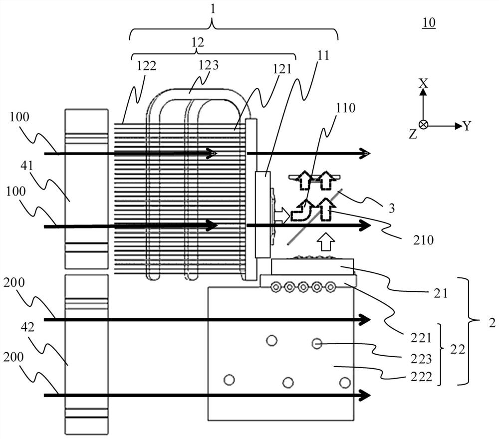
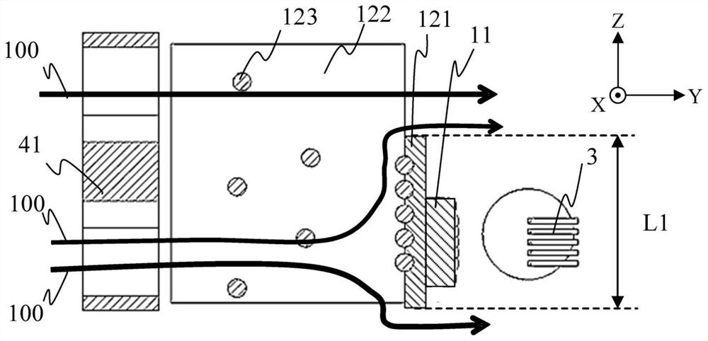
[0016] will now refer to Figure 1 to Figure 4 A light source device according to a first embodiment of the present invention will be described. figure 1 The cooling structure in the light source device 10 according to the present embodiment has been explained. figure 2 The light beam and the structure of the light source device 10 are explained. image 3 is along figure 2 A cross-sectional view taken along line A-A in . Figure 4 is along figure 2 A cross-sectional view taken along line B-B in .

[0017] Such as figure 1 and figure 2 As shown, the light source device 10 includes a first light source unit 1 , a second light source unit 2 and a combination unit 3 . The first light source unit 1 includes a first light source 11 having a plurality of solid-state light sources emitting laser beams (LD beams) and a first heat sink 12 holding and emitting heat from the first light sources 11 . The second light source unit 2 includes a second light source 21 having a plur...

no. 2 approach

[0041] will now refer to Figure 7 A light source device according to a second embodiment of the present invention will be described. Figure 7 The cooling structure of the light source device 10 a according to the present embodiment has been explained. The light source device 10a according to the present embodiment differs from the light source device 10 according to the first embodiment in that the first heat sink 12 and the second heat sink 22 are replaced by the first heat sink 120 and the second heat sink 220 . Other configurations, systems, and cooling airflows of the light source apparatus 10a are the same as those of the light source apparatus 10 according to the first embodiment, and thus descriptions thereof are omitted.

[0042] Such as Figure 7 As shown, the first heat sink 120 includes a base portion 1201 , a fin portion 1202 and a heat pipe 1203 . The second heat sink 220 has a base portion 2201 , a fin portion 2202 and a heat pipe 2203 . in addition, Figu...


PUM


Abstract

The present invention provides a light source apparatus and a projector. The light source apparatus includes a first light source, a second light source, a first radiator configured to hold the firstlight source and to radiate heat from the first light source, and a second radiator configured to hold the second light source and to radiate heat from the second light source. The first radiator includes a plurality of first radiating members to be cooled by air introduced from a first direction and superposed in a second direction. The second radiator includes a plurality of second radiating members to be cooled by air introduced from the first direction and superposed in a third direction. Each of the second direction and the third direction is orthogonal to the first direction. The seconddirection and the third direction are different from each other.

Description

technical field [0001] The present invention relates to a light source device and a projector including the light source device. Background technique [0002] Japanese Patent Laid-Open No. 2013-114980 discloses a light source device, which includes a first light source unit with a plurality of first solid-state light sources and a second light source unit with a plurality of second solid-state light sources, wherein the first light source unit and the second solid-state light source The emitting directions of the two light source units are orthogonal to each other, so as to realize high brightness and miniaturized structure. Japanese Patent Laid-Open No. 2014-139659 discloses a light source device that cools a light source unit using a cooling member such as a heat sink. [0003] In the light source device disclosed in Japanese Patent Laid-Open No. 2013-114980, the emission directions of the two light source units are orthogonal to each other. Therefore, in an attempt to a...

Claims


Application Information

Patent Timeline
Patent Type & Authority Applications(China)
IPC IPC(8): G03B21/16
CPCG03B21/16G03B21/2033G03B21/2013H04N9/3144
Inventor 野本谅
Owner CANON KK
Features
  • R&D
  • Intellectual Property
  • Life Sciences
  • Materials
  • Tech Scout
  • Unparalleled Data Quality
  • Higher Quality Content
  • 60% Fewer Hallucinations
Learn More