Inverter improved droop control method based on virtual synchronous machine technology

A technology of virtual synchronous machine and control method, which is applied in the direction of single-network parallel feeding arrangement, etc., can solve the problems of reactive power distribution accuracy, connection line impedance voltage drop and other problems, so as to aggravate voltage drop phenomenon and ensure the robustness of control , to achieve a reasonable distribution effect

Active Publication Date: 2021-01-19
NORTH CHINA ELECTRIC POWER UNIV (BAODING)
View PDF8 Cites 0 Cited by
  • Summary
  • Abstract
  • Description
  • Claims
  • Application Information

AI Technical Summary

Problems solved by technology

On the premise of realizing power decoupling, traditional droop control can only guarantee the reasonable distribution of active power, while the precision of reactive power distribution is obviously affected by the impedance voltage drop of the connecting line

Method used


Image

  • Inverter improved droop control method based on virtual synchronous machine technology
  • Inverter improved droop control method based on virtual synchronous machine technology
  • Inverter improved droop control method based on virtual synchronous machine technology

Examples


Embodiment Construction

[0055] The implementation of the present invention will be described in detail below in conjunction with the accompanying drawings and embodiments. It should be understood that the specific examples are only used to further explain the present invention, rather than limit the present invention.

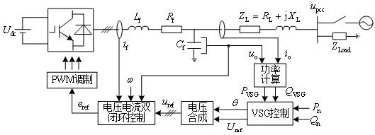
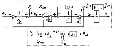
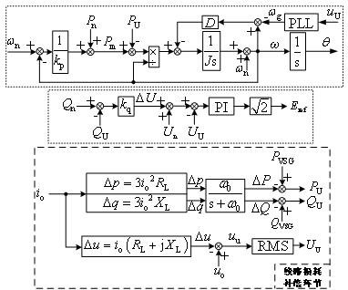
[0056] Such as figure 1 -7, the improved droop control method comprises the following steps:

[0057] Step 1: At the inverter port, that is, at the head end of the connection line between the microgrid and the public grid, collect the instantaneous value of the three-phase voltage u o and the instantaneous value of the three-phase current i o , to obtain the instantaneous active power at the head end of the line p VSG and instantaneous reactive power q VSG , obtained after filtering P VSG and Q VSG :

[0058] According to the following formula, the instantaneous active power at the head end of the connecting line is obtained p VSG and instantaneous reactive power q V...


PUM


Abstract

The invention discloses an inverter improved droop control method based on a virtual synchronous machine technology, and belongs to the field of low-voltage microgrid inverter control. The method comprises the following steps: acquiring active loss [delta]P and reactive loss [delta]Q of a connecting line according to impedance of the connecting line and a collected three-phase current instantaneous value io, and subtracting the active loss [delta]P and the reactive loss [delta]Q from active power PVSG and reactive power QVSG at the head end of the connecting line to obtain active power PU andreactive power QU at the tail end of the connecting line; obtaining the voltage drop [delta]u of the connection line according to the impedance of the connection line, the collected three-phase voltage instantaneous value uo and the collected three-phase current instantaneous value io; obtaining the effective value UU of the voltage at the head end of the connection line through RMS measurement after the difference between the voltage drop [delta]u and uo is obtained; obtaining the actual angular frequency omega at the same time; completing virtual synchronous machine control according to thedroop control equation and the rotor motion equation to obtain a voltage control instruction. According to the method disclosed in the invention, inverter steady-state power decoupling, user side droop characteristic and voltage controllability and reasonable power distribution during multi-machine parallel connection are realized.

Description

technical field [0001] The application relates to an inverter droop control method based on virtual synchronous machine technology, which belongs to the field of low-voltage microgrid inverter control. In particular, it relates to an improved droop control method for inverters based on virtual synchronous machine technology. Background technique [0002] In order to alleviate the contradiction between distributed power generation and large power grid, the concept of microgrid has been proposed and widely studied. The microgrid can not only run in parallel with the grid, but also be able to separate from the main grid and switch to island operation when the large grid fails or needs to be repaired within the plan. The control strategies for island operation that are widely used mainly include master-slave control and peer-to-peer control, among which the peer-to-peer control mode based on droop control has received more attention due to its high self-stability, autonomy and ...

Claims


Application Information

Patent Timeline
Patent Type & Authority Applications(China)
IPC IPC(8): H02J3/48H02J3/50
CPCH02J3/48H02J3/50
Inventor 颜湘武崔扬
Owner NORTH CHINA ELECTRIC POWER UNIV (BAODING)
Why Eureka
Try Eureka