Gynecological examination bed with massage function
A technology of obstetrics and gynecology and examination bed, which is applied in the field of obstetrics and gynecology examination bed with massage function, which can solve the problems of not being able to help women, relaxation and adjustment, etc.
- Summary
- Abstract
- Description
- Claims
- Application Information
AI Technical Summary
Problems solved by technology
Method used
Image
Examples
specific Embodiment approach 1
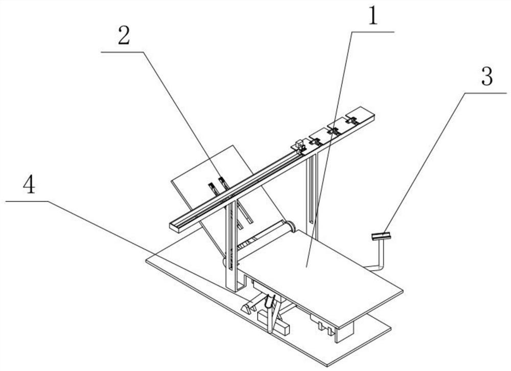
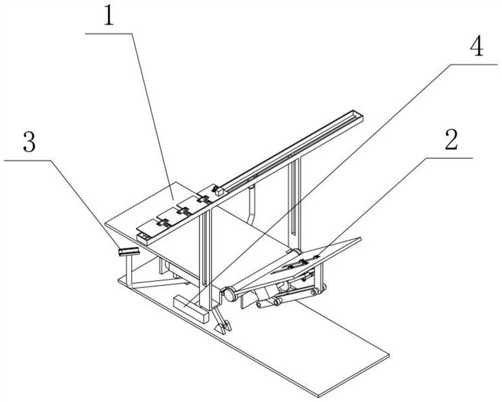
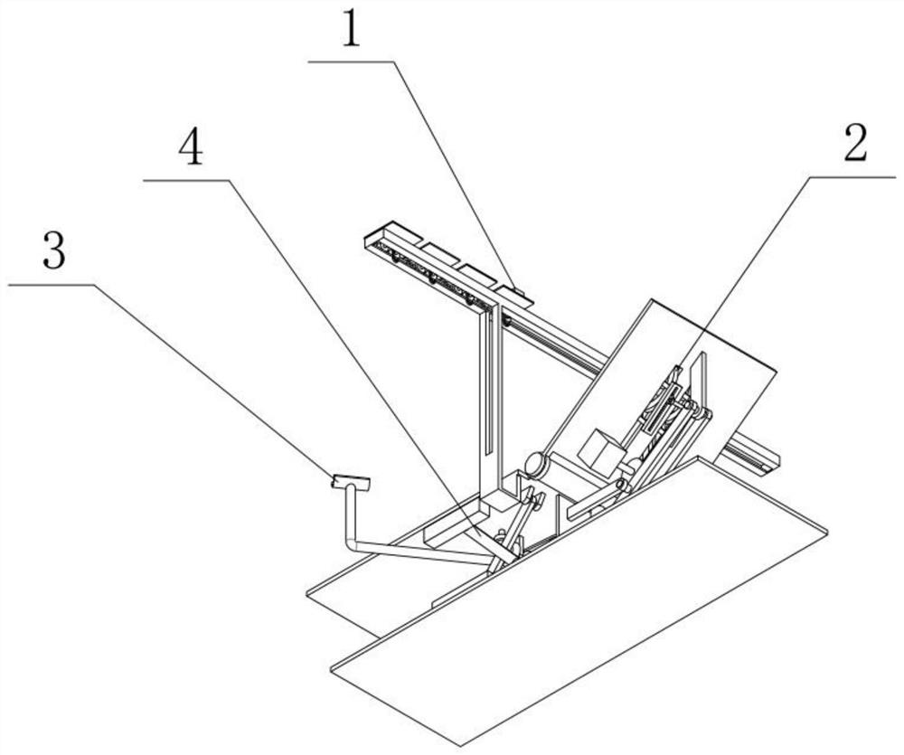
[0035] Combine below figure 1 , figure 2 , image 3 , Figure 4 , Figure 5 , Figure 6 , Figure 7 , Figure 8 , Figure 9 , Figure 10 , Figure 11 , Figure 12 , Figure 13 , Figure 14 , Figure 15 , Figure 16 , Figure 17 , Figure 18 , Figure 19 , Figure 20 To illustrate this embodiment, the present invention relates to an obstetrics and gynecology examination bed, more specifically, an obstetrics and gynecology examination bed with a massage function, including a backrest tilt adjustment and automatic shielding mechanism 1, a back massage mechanism 2, a leg rest Angle adjustment mechanism 3, hydraulic lifting mechanism 4, the device can adjust the back tilt angle, the device can automatically open and close the block curtain, the device can perform back massage, the device can change the opening and closing angle of the leg rest, and the device can automatically adjust the height.
[0036] The backrest inclination adjustment and automatic shielding...
specific Embodiment approach 2
[0038] Combine below figure 1 , figure 2 , image 3 , Figure 4 , Figure 5 , Figure 6 , Figure 7 , Figure 8 , Figure 9 , Figure 10 , Figure 11 , Figure 12 , Figure 13 , Figure 14 , Figure 15 , Figure 16 , Figure 17 , Figure 18 , Figure 19 , Figure 20 This embodiment will be described. This embodiment will further explain the first embodiment. The backrest tilt adjustment and automatic shielding mechanism 1 includes a bed body 1-1, a backrest 1-2, a trolley track 1-3, and two support seats-1. -4, support rod 1-5, two connecting rods 1-6, support seat 2 1-7, hydraulic cylinder 1-8, trolley platform 1-9, trolley platform 2 1-10, trolley platform 3 1 -11, trolley platform four 1-12, three connecting chains 1-13, motor one 1-14, transmission shaft one 1-15, chain one 1-16, sprocket one 1-17, gear shaft 1-18, Multiple shade hooks 1-19, multiple driven wheel shafts 1-20, two driving wheels 1-21, multiple driven wheels 1-22, driving shaft support ba...
specific Embodiment approach 3
[0040] Combine below figure 1 , figure 2 , image 3 , Figure 4 , Figure 5 , Figure 6 , Figure 7 , Figure 8 , Figure 9 , Figure 10 , Figure 11 , Figure 12 , Figure 13 , Figure 14 , Figure 15 , Figure 16 , Figure 17 , Figure 18 , Figure 19 , Figure 20 Describe this embodiment, this embodiment will further explain Embodiment 1, the described back massage mechanism 2 includes motor 2-1, transmission shaft 2-2, runner 2-3, connecting rod 2-4, connection Rod one 2-5, two chutes 2-6, multiple massage rollers 2-7, multiple fixed rods 2-8, two ear seats 2-9, two special-shaped sliders 2-10, motor two 2 -1 is rotationally connected with transmission shaft two 2-2, transmission shaft two 2-2 is connected with runner 2-3, runner 2-3 is hinged with connecting rod two 2-4, and connecting rod two 2-4 is connected with connecting rod One 2-5 is connected, connecting rod one 2-5 is hinged with two ear seats 2-9, two chute 2-6 is connected with a plurality o...
PUM
 Abstract
Description
Claims
Application Information
 - R&D
- Intellectual Property
- Life Sciences
- Materials
- Tech Scout
- Unparalleled Data Quality
- Higher Quality Content
- 60% Fewer Hallucinations
Browse by: Latest US Patents, China's latest patents, Technical Efficacy Thesaurus, Application Domain, Technology Topic, Popular Technical Reports.
© 2025 PatSnap. All rights reserved.Legal|Privacy policy|Modern Slavery Act Transparency Statement|Sitemap|About US| Contact US: help@patsnap.com


