Humidity and cleanliness control system for underground space environment

A control system and underground space technology, which is applied to control input related to air characteristics, space heating and ventilation control input, air conditioning system, etc., can solve problems such as low energy saving rate, long construction period, and low outlet air temperature, and achieve The effect of simple structure, complex equipment and low energy consumption

Active Publication Date: 2020-06-12
中国人民解放军火箭军工程设计研究院
View PDF8 Cites 0 Cited by
  • Summary
  • Abstract
  • Description
  • Claims
  • Application Information

AI Technical Summary

Problems solved by technology

Although the moisture content of the air in the space is reduced, the temperature in the underground space will be low and the relative humidity will be high due to the low temperature of the air outlet of the indoor unit. Processing method, high energy consumption of the system, low energy saving rate
[0006] In addition, if the air dehumidification mode commonly used in ground buildings is applied to the underground space, a large number of air duct systems need to be arranged, occupying the height of the underground space, the amount of air duct processing and installation is large, the project investment cost is high, and the construction period is long, which is not conducive to popularization and application

Method used


Image

  • Humidity and cleanliness control system for underground space environment
  • Humidity and cleanliness control system for underground space environment
  • Humidity and cleanliness control system for underground space environment

Examples


Embodiment 1

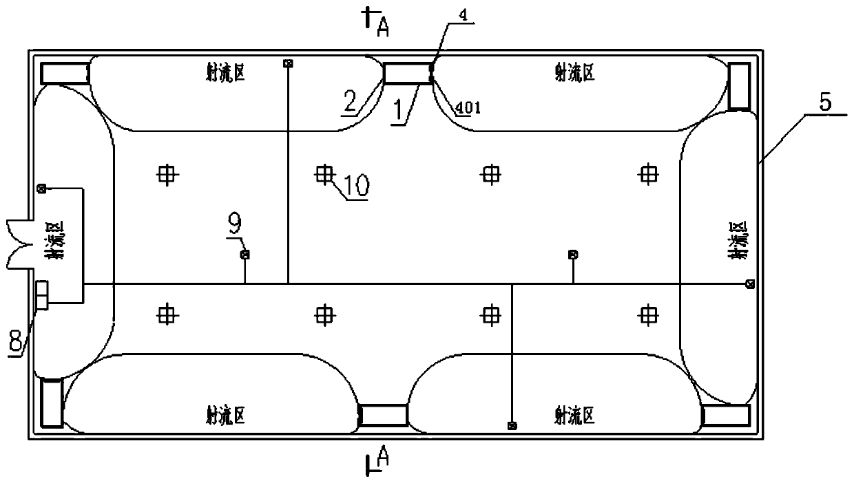
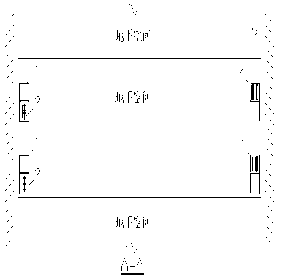
[0049] The control system for the ambient humidity of the walls around the underground space in this embodiment is as follows: Figure 1-4 As shown, six air dehumidification and purification devices 1 are arranged around the ground of the cuboid underground space and close to the wall 5, and form a circle at the same level. Specifically, four air dehumidification and purification devices 1 are arranged in a rectangular At the four top corners of the ground, the other two air dehumidification and purification devices 1 are respectively arranged at midpoints on the two long sides.

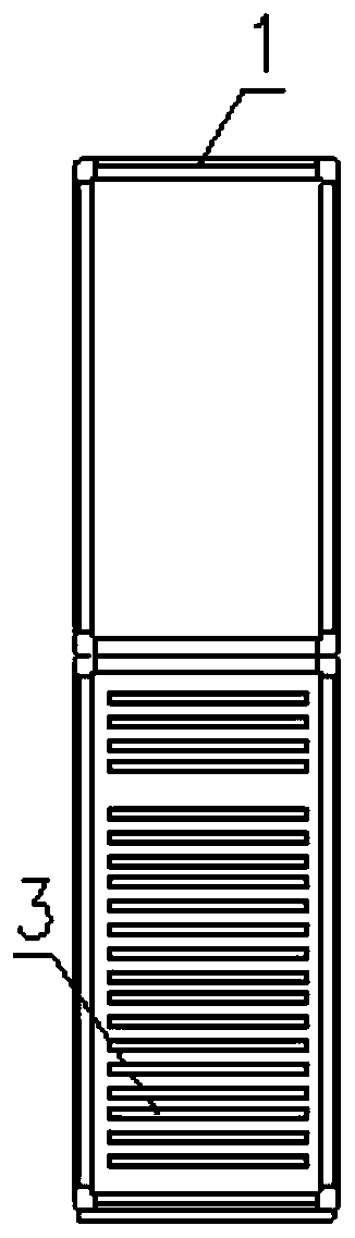
[0050] The front end of each air dehumidification and purification device 1 is provided with an attached nozzle 4 and a free nozzle 401, and the sides of four air dehumidification and purification devices 1 at the four corners are provided with two air inlets 2, and two long sides Two air inlets 2 are arranged at the rear ends of the two air dehumidification and purification devices 1 at the point po...

Embodiment 2

[0060] The control system for the ambient humidity of the roof of the underground space in this embodiment is as follows: Figure 5-8 As shown, nine air dehumidification and purification devices 1 are scattered and arranged on the lower surface of the roof 6 in the underground space, and the three air dehumidification and purification devices are connected end to end in a line, forming a row, that is, the attached nozzles of each air dehumidification and purification device 1 4 and the free nozzle 401 correspond to two air inlets 2 of the adjacent front air dehumidification and purification device, and each air dehumidification and purification device is separated by 25 meters.

[0061] The front end of each air dehumidification and purification device 1 is provided with an attached nozzle 4 and a free nozzle 401, and the rear end is provided with two air inlets 2, the attached nozzle 4 and the free nozzle 401 are arranged horizontally, and the air curtain is ejected horizontal...

Embodiment 3

[0065] The control system for the ambient humidity of the underground space ground in this embodiment is as follows: Figure 9-10 As shown, nine air dehumidification and purification devices 1 are scattered and arranged on the ground 7 of the underground space, and the three air dehumidification and purification devices are connected end to end in a line to form a row, that is, the attached nozzle 4 of each air dehumidification and purification device 1 Corresponding to the air inlet 2 of the air dehumidification and purification device in the adjacent front with the free nozzle 401, each air dehumidification and purification device is separated by 25 meters.

[0066] The front end of each air dehumidification and purification device 1 is provided with an attached nozzle 4 and a free nozzle 401, and the rear end is provided with two air inlets 2, the attached nozzle 4 and the free nozzle 401 are arranged horizontally, and the air curtain is ejected horizontally, The two air in...


PUM


Abstract

The invention provides a humidity and cleanliness control system for an underground space environment. The control system is characterized by comprising a plurality of air dehumidifying and purifyingdevices, the air dehumidifying and purifying devices are close to a wall surface, a top plate and / or the ground of underground space, air inlets are formed in the rear end and / or side surfaces of eachair dehumidifying and purifying device, at least one attaching nozzle and at least one free nozzle are arranged at the front end of each air dehumidifying and purifying device, the attaching nozzlesand the free nozzles are mounted side by side, and the at least one attaching nozzle and the at least one free nozzle of each air dehumidifying and purifying device correspond to the air inlets of theadjacent air dehumidifying and purifying device.

Description

technical field [0001] The invention belongs to the technical field of underground dehumidification, and in particular relates to a control system for the environmental humidity and cleanliness of an underground space. Background technique [0002] With the development of construction technology and the development and utilization of urban multi-functional spaces, the rational use of underground space not only facilitates people's lives, but also greatly expands people's activity space, such as underground parking lots, subways, military buildings, underground tunnels, etc. , the development and utilization of underground space resources has gradually become an important topic in urban modernization. Since the underground space is mostly a closed space or an environment with poor air circulation, the ambient temperature fluctuation range of the underground space is small, but the humidity is relatively high, with the characteristics of low temperature and high humidity. The...

Claims


Application Information

Patent Timeline
IPC IPC(8): F24F3/14F24F3/16F24F9/00F24F11/64F24F11/74F24F11/89F24F13/10F24F13/28F24F110/10F24F110/20
CPCF24F3/1405F24F9/00F24F13/10F24F13/28F24F2003/144F24F2009/007F24F11/64F24F11/74F24F11/89F24F2110/10F24F2110/20F24F8/10F24F8/167
Inventor 谭可可苏辉林来豫方仲元涂江峰孙海石
Owner 中国人民解放军火箭军工程设计研究院
Why Eureka
Try Eureka