Manual steaming pad punching and forming device

A forming device and transmission technology, applied in the field of manual steam pad punching forming device, can solve the problems of low safety and low work efficiency, and achieve the effect of improving work efficiency and facilitating work

Inactive Publication Date: 2021-01-22
张彪
View PDF0 Cites 0 Cited by
  • Summary
  • Abstract
  • Description
  • Claims
  • Application Information

AI Technical Summary

Problems solved by technology

[0004] In order to overcome the shortcomings of low work efficiency and low safety of manual feeding and retrieving, the technical problem to be solved is to provide a method that can complete automatic blanking, automatic pushing, automatic stamping and forming of circular aluminum plates. Manual steam pad punching and forming device with automatic ejection function

Method used


Image

  • Manual steaming pad punching and forming device
  • Manual steaming pad punching and forming device
  • Manual steaming pad punching and forming device

Examples


Embodiment 1

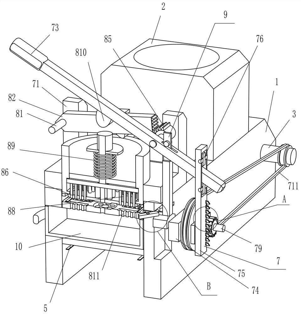
[0058] A manual steam pad punching forming device, such as figure 1 As shown, it includes a workbench 1, a blanking table 2, a first rotating shaft 3, a drum 4, a conveyor belt 5, a pusher block 6, a transmission device 7 and a stamping device 8, and a blanking table is provided on the left side of the top of the workbench 1. 2. The upper part of the left and right sides of the workbench 1 is symmetrically rotated and provided with a first rotating shaft 3, and a rotating drum 4 is arranged on the first rotating shaft 3, and a conveyor belt 5 is arranged on the front and rear sides of the rotating drum 4, and the conveyor belt 5 is equipped with Pushing blocks 6 are evenly arranged, a transmission device 7 is provided between the middle part of the workbench 1 and the first rotating shaft 3 on the left side, and a stamping device 8 is provided on the transmission device 7 .

[0059] When people want to punch and shape the steaming mat, all the circular aluminum plates are put ...

Embodiment 2

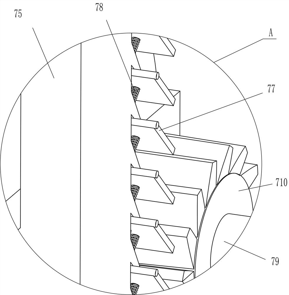
[0061] On the basis of Example 1, such as figure 1 , figure 2 , image 3 and Figure 4As shown, the transmission device 7 includes a first support frame 71, a second rotating shaft 72, a pressure rod 73, a second support frame 74, a transmission plate 75, a guide wheel 76, a pawl 77, a first return spring 78, a third rotating shaft 79. The ratchet 710 and the transmission assembly 711, the first support frame 71 is arranged in the middle of the top of the workbench 1, the upper rear side of the first support frame 71 is rotated and the second rotating shaft 72 is provided, and the middle of the second rotating shaft 72 is provided with a pressing rod 73, The upper part of the rear side of the workbench 1 is provided with a second support frame 74, and the right side of the second support frame 74 is slidably provided with a drive plate 75, and the upper part of the drive plate 75 is symmetrically rotated up and down and is provided with a guide wheel 76. The upper portion ...

Embodiment 3

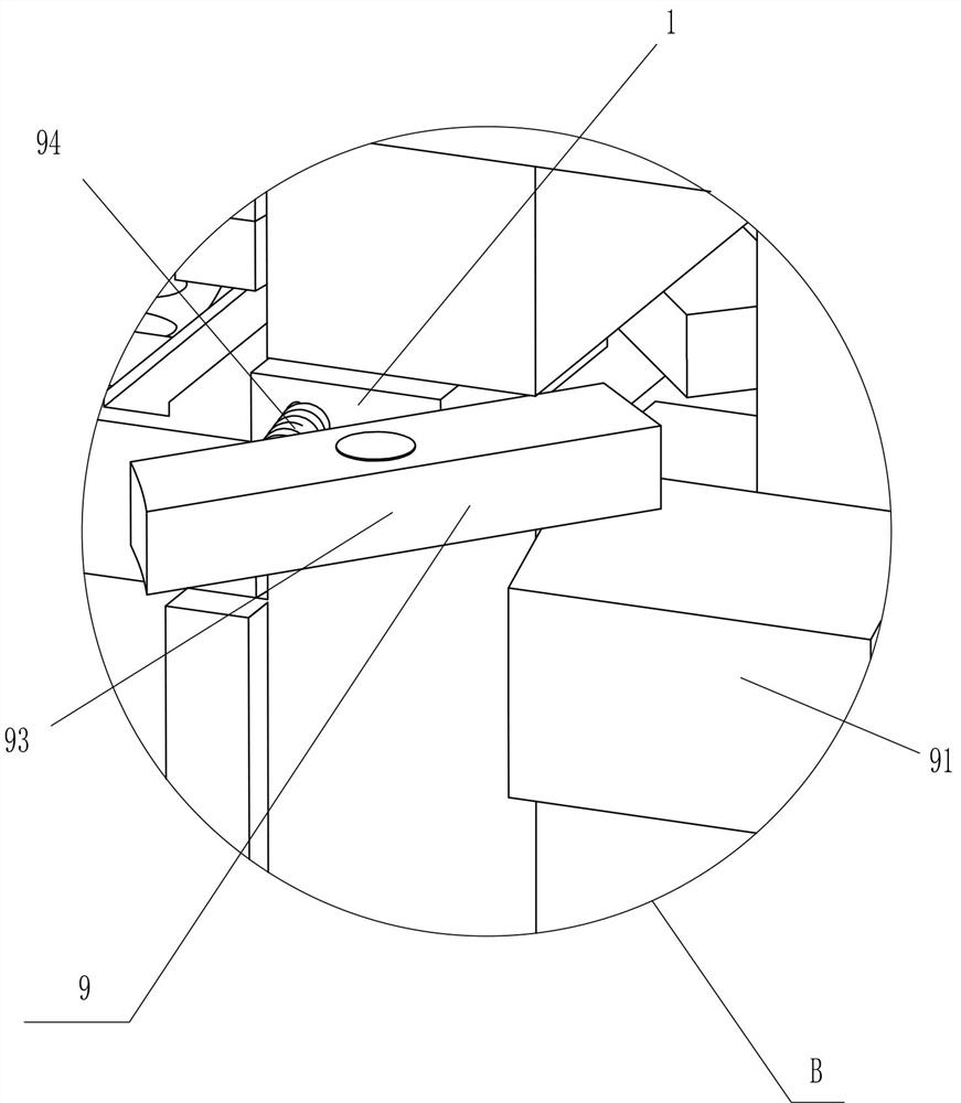
[0066] On the basis of Example 2, such as figure 2 and Figure 5 As shown, positioning device 9 is also included, and positioning device 9 includes special-shaped block 91, rotating column 92, positioning block 93 and the fifth return spring 94, and the second support frame 74 front side is provided with special-shaped block 91, and special-shaped block 91 tops Through the rear portion of the depression bar 73, the top of the special-shaped block 91 is rotatably provided with a rotating column 92, and the right side of the workbench 1 rear portion is symmetrically rotated to be provided with a positioning block 93. The positioning block 93 is extruded with the special-shaped block 91, and the positioning block A fifth return spring 94 is arranged between the front part of the opposite side of 93 and the workbench 1 .

[0067] After the pusher block 6 pushes the circular aluminum plate to move rightward to the top of the forming plate 811, when the rocking pressure bar 73 mov...


PUM


Abstract

The invention relates to a punching and forming device, in particular to a manual steaming pad punching and forming device. The manual steaming pad punching and forming device has functions of automatically blanking, pushing, punching, forming and discharging circular aluminum plates. The manual steaming pad punching and forming device comprises a worktable, a blanking table, first rotating shafts, rotating cylinders, conveying belts and pushing blocks, wherein the blanking table used for placing circular aluminum plates is arranged on one side of the top of the worktable;the first rotating shafts are symmetrically and rotationally arranged at the upper parts of the two sides of the interior of the worktable;the rotating cylinders are arranged on the first rotating shafts;the conveying belts are arranged on two sides of a part between the rotating cylinders; and the pushing blocks are uniformly arranged on each conveying belt. Through cooperation of a transmission device and a stampingdevice, the circular aluminum plates can be automatically blanked, punched, formed and discharged; the manufactured steaming pads are consistent in shape and size; and the working efficiency of people is improved.

Description

technical field [0001] The invention relates to a punching and forming device, in particular to a manual steaming mat punching and forming device. Background technique [0002] When cooking pasta, in order to prevent the pasta from sticking to the steaming plate, a steaming mat is usually placed on the steaming plate. According to the material, the steaming mat can be divided into bamboo grass, cotton yarn, metal and paper, and some Vendors use plastic woven bags packed with fertilizer or cement as steaming mats. Generally, steaming mats used at home are made of aluminum, because aluminum steaming mats heat quickly and are convenient, and as long as there is water in them, they will not melt. So deeply loved by the people. [0003] According to the current technology, most of the production methods of steaming pads are punched by machine tools. People need to manually put the circular aluminum plate into the machine tool, then start the machine tool to stamp the circular al...

Claims


Application Information

Patent Timeline
IPC IPC(8): B21D28/26B21D28/04B21D43/04B21D45/02B21D43/20
CPCB21D28/04B21D28/26B21D43/04B21D43/20B21D45/003B21D45/02
Inventor 张彪
Owner 张彪
Why Eureka
Try Eureka