Drilling mechanical equipment

A technology for mechanical equipment and drilling pipes, which is applied to drilling equipment, drilling equipment and methods, rotary drilling rigs, etc., can solve the problems of inability to facilitate down-pressure drilling of drilling pipes, and achieve the effect of facilitating down-pressure drilling.

Inactive Publication Date: 2021-01-22
王旭
View PDF11 Cites 0 Cited by
  • Summary
  • Abstract
  • Description
  • Claims
  • Application Information

AI Technical Summary

Problems solved by technology

But this patent can't facilitate the drill pipe to press down and drill

Method used


Image

  • Drilling mechanical equipment
  • Drilling mechanical equipment
  • Drilling mechanical equipment

Examples


specific Embodiment approach 1

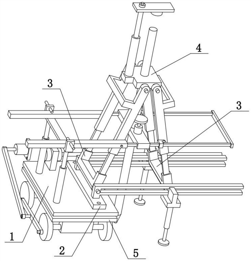
[0031] Combine below Figure 1-10 Describe this embodiment, the present invention relates to the field of drilling, more specifically a drilling mechanical equipment, including a top seat 4, a ring 401, a pressing piece 402, an oil cylinder III 403 and a drilling pipe 404, and the present invention can facilitate the drilling of the drilling pipe 404 Pressure drilling.

[0032] The top seat 4 is vertically slidably connected with a drilling pipe 404, the upper side of the top seat 4 is fixedly connected with an oil cylinder III403, the upper end of the oil cylinder III403 is rotatably connected with an oil cylinder III403, and the lower side of the oil cylinder III403 is provided with a ring 401, the ring 401 is located at the upper end of the drilling pipe 404, and the drilling pipe 404 is composed of multiple segments, which are sequentially connected by threads. Oil cylinder III 403 can drive pressing piece 402 to move down when stretching, and then ring 401 is inserted on...

specific Embodiment approach 2

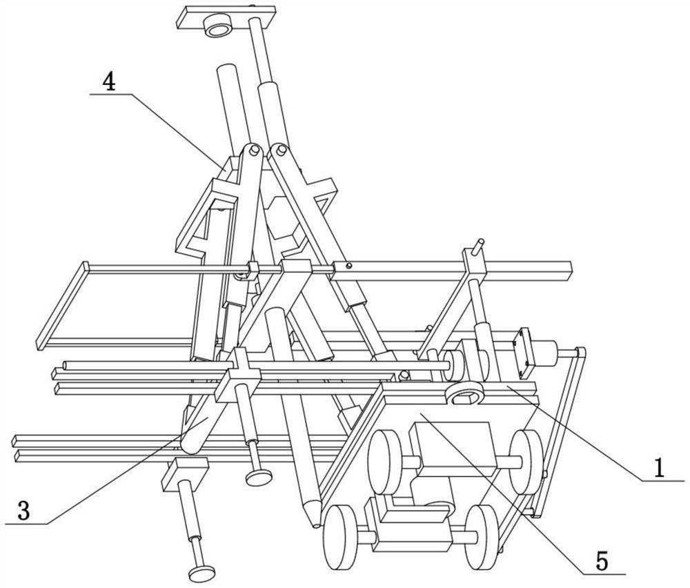
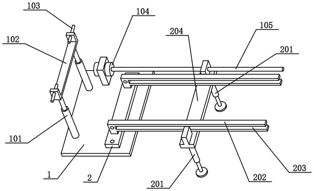
[0034] Combine below Figure 1-10 To illustrate this embodiment, the drilling mechanical equipment also includes a horizontal bar 301, an H-shaped frame 302, a right connecting rod 303, a horizontal bar 304 and a rotating seat block 305, and one H-shaped frame 302 is arranged on the left and right, and two H-shaped frames The upper part of 302 is respectively hinged on the left and right ends of the top seat 4, and one horizontal bar 301 is respectively arranged at the front and rear, and the right ends of the two horizontal bars 301 are respectively hinged at the front and rear sides of the H-shaped frame 302 on the left side, and the two horizontal bars The right end of 301 is fixedly connected with a crossbar 304, and the front and rear sides of the H-shaped frame 302 on the right side are rotatably connected with a rotating seat block 305, and the two crossbars 304 are respectively slidably connected to the two rotating seat blocks in the left and right direction. 305, a r...

specific Embodiment approach 3

[0036] Combine below Figure 1-10To illustrate this embodiment, the drilling mechanical equipment also includes a middle sliding seat 405, a motor II 406 and a friction wheel 407. A motor II406 is fixedly connected, and a friction wheel 407 is fixedly connected to the output shaft at the upper end of the motor II406, and the friction wheel 407 and the drilling pipe 404 are frictionally driven. The middle sliding seat 405 can slide left and right between the two cross bars 304, adapting to the opening and closing between the two H-shaped frames 302, the motor II406 can drive the friction wheel 407 to rotate, and when the friction wheel 407 rotates, it drives the drilling pipe 404 to Its own axis rotates as a shaft, thereby facilitating the drilling of the drilling pipe 404 .


PUM


Abstract

The invention relates to the field of drilling, in particular to drilling mechanical equipment. The equipment comprises a top base, a circular ring, a pressing piece, an oil cylinder III and a drilling pipe, and can facilitate downward pressing drilling of the drilling pipe. The drilling pipe is vertically connected to the top base in a sliding mode, the oil cylinder III is fixedly connected to the upper side of the top base, an oil cylinder III is rotatably connected to the upper end of the oil cylinder III, the circular ring is arranged on the lower side of the oil cylinder III and located at the upper end of the drilling pipe, and the drilling pipe is composed of a plurality of sections of split bodies which are sequentially connected through threads. The drilling mechanical equipment further comprises transverse strips, H-shaped frames, right connecting rods, transverse rods and rotating seat blocks, wherein the H-shaped frames are arranged on the left and right respectively, the upper portions of the two H-shaped frames are hinged to the left end and the right end of the top base respectively, the transverse strips are arranged in front and back respectively, the right ends ofthe two transverse strips are hinged to the front side and the rear side of the H-shaped frame located on the left side, the right ends of the two transverse strips are fixedly connected with the transverse rods correspondingly, and the front side and the rear side of the H-shaped frame located on the right side are rotatably connected with the rotating seat blocks correspondingly.

Description

technical field [0001] The invention relates to the field of drilling, more specifically to a drilling mechanical equipment. Background technique [0002] The application number is CN202020168009.4, which discloses a new type of rock bolter. This utility model belongs to the technical field of coal mine machinery. The positioning device is arranged on the frame for positioning the position of the frame, the rotary assembly is arranged on the frame, the traveling wheel assembly is arranged on the frame, the drilling assembly is arranged on the rotary assembly, and the rotary assembly is used to adjust the angle of the drilling assembly; The drilling assembly includes: a drilling driving device and a propulsion assembly. The drilling driving device is used to drive the drill pipe. The propulsion assembly is arranged on the rotary assembly. The drilling driving device is arranged on the propulsion assembly. Through the above technical solution, the problem of poor effect of dr...

Claims


Application Information

Patent Timeline
Patent Type & Authority Applications(China)
IPC IPC(8): E21B7/02E21B15/00E21B49/02E21B3/02
CPCE21B7/02E21B15/00E21B49/02E21B3/02
Inventor 王旭刘忠元齐永高
Owner 王旭
Why Eureka
Try Eureka