
Super high pressure booster centrifugal pump

A centrifugal pump, ultra-high pressure technology, applied in the direction of pumps, pump components, pump control, etc., can solve the problem that the pump cannot be used effectively as a series booster pump, to achieve enhanced rigidity, improved sealing effect, and reduced axial length effect of size

Active Publication Date: 2022-04-15
重庆水泵厂有限责任公司
View PDF11 Cites 0 Cited by
  • Summary
  • Abstract
  • Description
  • Claims
  • Application Information

AI Technical Summary

Problems solved by technology

[0006] Aiming at the above-mentioned deficiencies of the prior art, the technical problem to be solved by the present invention is to provide an ultra-high pressure supercharged centrifugal pump, so as to avoid the problem that the existing pumps cannot be effectively used as series supercharged pumps, especially the previous pumps connected in series When the water outlet pressure is already high, the pressure bearing and sealing effect are good, and the effect of use is effectively guaranteed.

Method used


Image

  • Super high pressure booster centrifugal pump
  • Super high pressure booster centrifugal pump
  • Super high pressure booster centrifugal pump

Examples


Embodiment Construction

[0029] The specific implementation manners of the present invention will be further described in detail below in conjunction with the accompanying drawings.

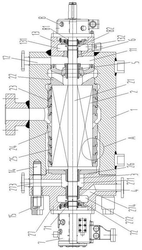
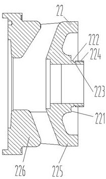
[0030] See figure 1, the ultra-high pressure booster centrifugal pump of the specific embodiment, the ultra-high pressure booster centrifugal pump, comprises a sleeve-shaped pump body 1, and an inner core assembly 2 is installed in the pump body 1 along its axial direction, and the inner core assembly 2 Including the pump shaft 21, the pump shaft 21 is provided with an impeller part and a pump cover 27, the impeller part is located in the pump body 1, and the impeller part includes a water inlet section 22 arranged in sequence along the axial direction of the pump shaft 21, a primary guide The flow section 23, the water outlet section 24, the secondary diversion section 25 and the high-pressure water inlet section 26, the pump cover 27 is fastened on one end of the pump body 1 and is located outside the high-pressure wat...


PUM


Abstract

The invention relates to an ultra-high pressure supercharged centrifugal pump. The pump body is equipped with an inner core assembly. The inner core assembly includes a pump shaft. The pump shaft is provided with an impeller part and a pump cover. The impeller part is located in the pump body and includes a water inlet section, For the high-pressure water inlet section, the pump cover is buckled on one end of the pump body and the surface facing the high-pressure water inlet section is in close contact with the high-pressure water inlet section; the pump shaft passes through the high-pressure water inlet section and then passes through the first part of the pump cover. 1. The second low-pressure chamber; the other end of the pump shaft passes through the water inlet section and passes through the pump body in turn. There are third and fourth low-pressure chambers. The third low-pressure chamber and the water inlet channel of the water inlet section pass through the first The three spiral seals are connected; the fourth low-pressure chamber and the third low-pressure chamber are connected through the fourth spiral seal; the first and third low-pressure chambers are respectively connected to the balance pipeline, and the second and fourth low-pressure chambers are respectively connected to the drain holes. The pump has a symmetrical sealing structure on the driving end and the non-driving end, and adopts multi-stage spiral seals to depressurize and discharge in turn, effectively ensuring that the two ends are sealed and leak-free during operation.

Description

technical field [0001] The invention belongs to the technical field of non-variable pumps, in particular to an ultra-high pressure supercharged centrifugal pump. Background technique [0002] A centrifugal pump is a pump that delivers fluid by the centrifugal force generated when the impeller rotates. The fluid is sucked in from the water inlet and pumped out from the water outlet; on the pump shaft with multi-stage impellers arranged in one direction, a balance drum and pump casing are usually installed. Correspondingly set the pressure difference chamber and connect the balance water pipe to balance the axial force transmitted by the impeller rotation on the pump shaft through the balance drum, as described in the prior art such as CN208416966U. Generally speaking, the waterway section from the water inlet to the first-stage impeller is a low-pressure chamber. As the impeller works, the water pressure increases step by step, and the water outlet is a high-pressure chamber....

Claims


Application Information

Patent Timeline
Patent Type & Authority Patents(China)
IPC IPC(8): F04D1/00F04D29/42F04D29/10F04D29/12F04D29/14F04D29/44F04D29/66F04D15/00
CPCF04D1/00F04D29/426F04D29/106F04D29/126F04D29/146F04D29/445F04D29/669F04D15/0088
Inventor 李文伟罗绍华白小榜杨海龙温询刘磊闫丽君
Owner 重庆水泵厂有限责任公司
Learn More