Semi-active shock absorber

A semi-active shock absorber and main valve core technology, which is applied in the direction of shock absorbers, shock absorbers, springs/shock absorbers, etc., can solve the high machining accuracy requirements of proportional electromagnets and the difficulty of localization of semi-active shock absorbers , damping characteristics can not be adjusted and other problems, to achieve the effect of reducing the processing accuracy requirements, continuous adjustment and control, stable and reliable operation

Pending Publication Date: 2021-01-22
成都九鼎科技(集团)有限公司
View PDF0 Cites 2 Cited by
  • Summary
  • Abstract
  • Description
  • Claims
  • Application Information

AI Technical Summary

Problems solved by technology

The ideal shock absorber characteristics should be able to adapt to the above-mentioned different driving conditions and the driver's requirements. However, the most commonly used suspension shock absorbers so far are traditional passive shock absorbers, and their damping characteristics cannot be adjusted. A compromise between handling and comfort; the damping force of the traditional semi-active shock absorber controlled by a proportional valve can be automatically adjusted according to the road conditions, but the proportional solenoid used in the proportional valve of this shock absorber High machining accuracy is required, and the controller used is complex in structure, and its related technology is monopolized by foreign countries, which brings great difficulties to the localization of the semi-active shock absorber controlled by the proportional valve.

Method used


Image

  • Semi-active shock absorber
  • Semi-active shock absorber
  • Semi-active shock absorber

Examples


Embodiment Construction

[0038] The present invention will be further described below in conjunction with the accompanying drawings and specific embodiments.

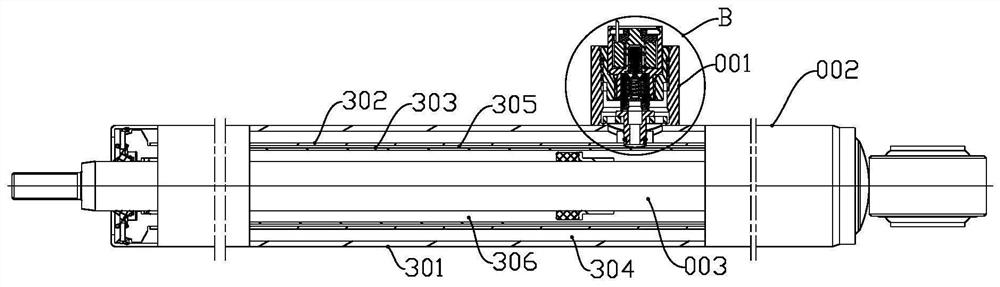
[0039] refer to figure 1 , the semi-active shock absorber in this embodiment includes an oil cylinder assembly 002, a connecting rod piston assembly 003, a bottom valve assembly and a digital proportional valve 001; wherein, the oil cylinder assembly includes an outer cylinder 301, an inner cylinder 302 and working cylinder 303, an oil storage cavity 304 is formed between the inner cylinder 302 and the outer cylinder 301, an intermediate cavity 305 is formed between the inner cylinder 302 and the working cylinder 303, and a working cylinder 303 is formed cavity 306 . The connecting rod piston assembly 003 is arranged in the working cylinder 303 , and the bottom valve assembly is arranged at one end of the inner cylinder 302 .

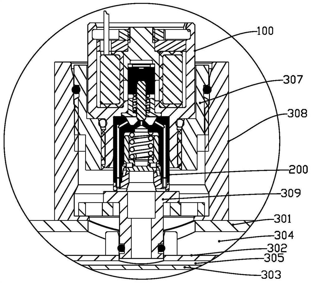
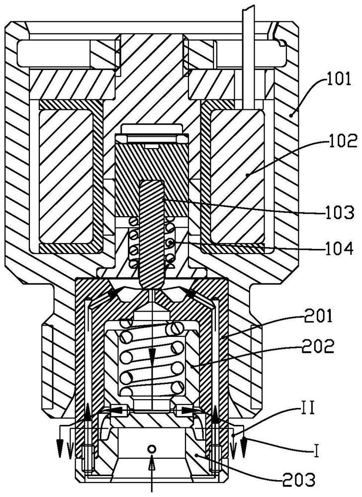
[0040] Such as figure 2 , 3 As shown in and 4, the digital proportional valve in this embodiment includes a switc...


PUM


Abstract

The invention discloses a semi-active shock absorber. The semi-active shock absorber comprises an oil cylinder assembly, a connecting rod piston assembly, a bottom valve assembly and a digital proportional valve, wherein a main valve assembly is provided with a first oil way and a second oil way; the oil inlet end of the first oil way and the oil inlet end of the second oil way communicate with amiddle cavity; the oil outlet end of the first oil way and the oil outlet end of the second oil way communicate with an oil storage cavity; when a coil assembly is not powered on, the first oil way isin a connected state, the second oil way is in a disconnected state, and the middle cavity communicates with the oil storage cavity through the first oil way; and when the coil assembly is powered on, an armature push rod assembly blocks the first oil way, the first oil way is in a disconnected state, and the middle cavity communicates with the oil storage cavity through the second oil way. The digital proportional valve is adopted for adjusting and controlling the throttling area of shock absorber oil liquid, and the damping force of the shock absorber is adjusted; and by controlling the duty ratio of input signals, the throttling area of the proportional valve can be continuously and freely adjusted, and the damping force of the shock absorber is continuously adjusted and controlled.

Description

technical field [0001] The invention relates to the technical field of shock absorbers, in particular to a semi-active shock absorber. Background technique [0002] The requirements of car ride comfort / ride comfort and handling stability on suspension shock absorber characteristics vary with specific driving conditions such as road surface, load, vehicle speed and vehicle motion state, and also vary with drivers. The ideal shock absorber characteristics should be able to adapt to the above-mentioned different driving conditions and the driver's requirements. However, the most commonly used suspension shock absorbers so far are traditional passive shock absorbers, and their damping characteristics cannot be adjusted. A compromise between handling and comfort; the damping force of the traditional semi-active shock absorber controlled by a proportional valve can be automatically adjusted according to the road conditions, but the proportional solenoid used in the proportional va...

Claims


Application Information

Patent Timeline
Patent Type & Authority Applications(China)
IPC IPC(8): F16F9/512F16F9/34
CPCF16F9/34F16F9/5123F16F9/5126F16F2222/12
Inventor 秦雪梅唐兵李国华侯平严茂谢毅
Owner 成都九鼎科技(集团)有限公司
Why Eureka
Try Eureka