Logic clock synchronization method and device and central time service cluster

A logic clock and cluster technology, applied in the field of distributed systems, can solve problems such as affecting the performance of distributed systems and blocking tasks of distributed systems.

Active Publication Date: 2021-01-22
BEIJING KINGSOFT CLOUD NETWORK TECH CO LTD
View PDF4 Cites 2 Cited by
  • Summary
  • Abstract
  • Description
  • Claims
  • Application Information

AI Technical Summary

Problems solved by technology

[0005] In the above-mentioned related technologies, when the master node and the standby node are synchronizing, the master node will not respond to the timing request before receiving the confirmation message about forced synchronous replication fed back by the standby node. Therefore, in this case, the Block the tasks in the distributed system, thereby affecting the performance of the distributed system

Method used


Image

  • Logic clock synchronization method and device and central time service cluster
  • Logic clock synchronization method and device and central time service cluster
  • Logic clock synchronization method and device and central time service cluster

Examples


example 1

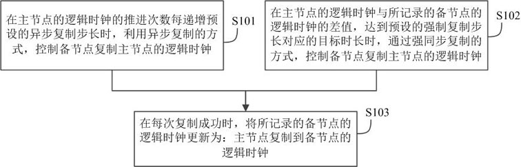
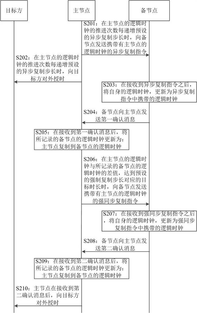
[0115] Example 1: The logical clock of the master node is 580, and the logical clock of the standby node and the logical clock of the standby node recorded in the master node are both 550. At this time, when the master node receives the timing request a, it advances its own logical clock to 581, Further, the primary node fails. In this way, after the standby node is promoted to master, in order to respond to the timing request a, the logical clock of the standby node for external timing for the first time is: 550+500=1050. Therefore, since 1050>580, the logical clock of the standby node for the first external time service after being promoted to master is not go back.

example 2

[0116] Example 2: The logical clock of the primary node is 580, the logical clock of the standby node recorded by the primary node is 100, and the logical clock of the standby node is 550. At this time, the primary node receives the timing request b and advances its own logical clock 581, and then, the primary node fails. In this way, after the standby node is promoted to the master, in order to respond to the timing request b, the logical clock of the standby node for the first external time service is: 550+500=1050. Therefore, since 1050>580, the logical clock of the standby node for the first external time service after being promoted to the master is not go back.

example 3

[0117] Example 3: The logical clock of the primary node is 580, the logical clock of the standby node recorded by the primary node is 100, and the logical clock of the standby node is 100. At this time, when the primary node receives the timing request c, it advances its own logical clock 581, and then, the primary node fails. In this way, after the standby node is promoted to master, in order to respond to the timing request c, the logical clock of the standby node for external timing for the first time is: 100+500=600. Therefore, since 600>580, the logical clock for the first external timing of the standby node after being promoted to master is not go back.


PUM


Abstract

The embodiment of the invention provides a logic clock synchronization method and device and a central time service cluster, and relates to the technical field of distributed systems. The method is applied to a main node in a central time service cluster of a distributed system, and comprises the following steps of: controlling a standby node to copy a logic clock of the main node in an asynchronous copying mode when the advancing frequency of the logic clock of the main node is increased by a preset asynchronous copying step length each time; and when the difference value between the logic clock of the main node and the recorded logic clock of the standby node reaches the target duration corresponding to the preset forced copying step length, controlling the standby node to copy the logicclock of the main node in a strong synchronous copying mode, and updating the recorded logic clock of the standby node into the logic clock of the main node copied to the standby node when the copying is successful each time. Compared with the prior art, by applying the method provided by the embodiment of the invention, the task in the distributed system can be prevented from being blocked, so that the performance of the distributed system is improved.

Description

technical field [0001] The invention relates to the technical field of distributed systems, in particular to a logical clock synchronization method and device and a central timing cluster. Background technique [0002] At present, a central timing cluster is usually set up in a distributed system to realize the logical time advancement of the distributed system, so as to clearly and accurately mark the time sequence between tasks. [0003] In order to ensure the normal operation of the central timing cluster, a master node and a backup node can be set in the central timing cluster, so that when the master node fails, the backup node can take over from the master node for external timing. In addition, in order to ensure that the standby node takes over the master node's external time service and meets the requirement of no time rollback, there is a requirement for logical clock synchronization between the master node and the slave node. [0004] In order to meet the above-me...

Claims


Application Information

Patent Timeline
Patent Type & Authority Applications(China)
IPC IPC(8): H04L29/08H04J3/06
CPCH04L67/10H04L67/1095H04J3/0638
Inventor 王天宇
Owner BEIJING KINGSOFT CLOUD NETWORK TECH CO LTD
Why Eureka
Try Eureka